
Best Practices for Deployments
using DCB and RoCE

2 WHITE PAPER | Best Practices for Deployments using DCB and RoCE
Introduction..................................................................................................................................................................................................................................
Converged Networks...................................................................................................................................................................................................................
RoCE................................................................................................................................................................................................................................................
RoCE and iWARP Comparison...................................................................................................................................................................................................
RoCE Benefits for the Data Center............................................................................................................................................................................................
RoCE Evaluation Design..............................................................................................................................................................................................................
RoCE Evaluation Results...........................................................................................................................................................................................................
RoCE Evaluation Observations...............................................................................................................................................................................................
Conclusion....................................................................................................................................................................................................................................
References...................................................................................................................................................................................................................
Appendix A: Switch Configuration Settings.........................................................................................................................................................................
3
3
3
4
5
6
9
13
15
15
16
Contents

3 WHITE PAPER | Best Practices for Deployments using DCB and RoCE
Introduction
Data center administrators are facing increased demands to accelerate applications and improve network performance. This requirement applies to
both large scale and discrete data centers that need high throughput and low latency to support distributed architectures. Part of the problem can
be solved by deploying new generations of servers that provide faster CPU cycles and expanded memory capabilities. These new systems are often
combined with the transition to 10Gb Ethernet (10GbE) technology that provides a 10x increase in network bandwidth and an expanded selection
of supported protocols to fully enable server capabilities.
The optimum solution is more than just faster CPUs and raw bandwidth. The best approach is to support multiple protocols for networking and
storage over a single converged infrastructure and to use that infrastructure to optimize the use of server and storage resources. This white paper
will provide an overview of converged networks with a focus on technologies that enable remote direct memory access (RDMA) over Converged
Ethernet (RoCE), which is ideal for high-performance and cluster deployments.
In addition, the white paper also includes best practices for lossless network design and presents performance data that supports the business case
to justify RoCE deployments. Tests were completed using Emulex OCe14000 Converged Network Adapters (CNAs) and Cisco Nexus 2300 Fabric
Extender and Nexus 5600 series switches.
Converged Networks
The capability to optimally support converged network and storage trac on 10GbE and faster networks is based on Data Center Bridging (DCB)
that is defined in a set of Institute of Electrical and Electronics Engineers (IEEE) standards
1
. These include:
• Data Center Bridging Capabilities Exchange Protocol (DCBX): Discovery and exchange of capabilities to ensure consistent configuration
between network neighbors. (IEEE 802.1az)
• Priority-based Flow Control (PFC): Link level flow control mechanism that can be controlled independently for each class of network service.
This enables lossless Ethernet, eliminating the need to re-transmit packets of congested networks. (IEE 802.1Qbb)
• Enhanced Transmission Selection (ETS): Defines a common management framework to assign bandwidth for each class of network service.
(IEEE 802.1Qaz)
Based on these standards, Fibre Channel over Ethernet (FCoE) has become an important technology that allows data centers to reduce costs by
converging storage and Transmission Control Protocol /Internet Protocol (TCP/IP) trac on a single 10GbE infrastructure. Lossless design principles
and DCB protocols are also highly recommended (although not required) for dedicated high performing iSCSI storage networks. The next step in
network convergence is performance gains that can be achieved by supporting RDMA transfer.
RoCE
Direct memory access (DMA) has been a built-in feature of personal computer (PC) architecture since the introduction of the original PCs. DMA
allows hardware subsystems such as disk drive controllers, sound cards, graphics cards and network cards to access system memory to perform data
read/write without using CPU processing cycles.
As shown in Figure 1, RDMA extends that capability by allowing network adapters to do server-to-server data transfer data between application
memory. Using zero-copy functionality, an application can perform an RDMA read or write request that delivers data directly to the network,
eliminating the need to copy data between application memory and the data buers in the OS. The end result is reduced latency and faster message
transfer.
1
http://www.ieee802.org/1/pages/dcbridges.html

4 WHITE PAPER | Best Practices for Deployments using DCB and RoCE
RDMA is a proven technology with the original specification dating back to 1999. It is widely used to power the most demanding high-performance
and low latency systems and is supported by a broad spectrum of OSes and applications. The first commercial implementation of RDMA was with
InfiniBand (IB) fabrics. Although RDMA over IB delivers performance improvements, it comes with a high cost to purchase and support a dedicated
IB network. With the deployment of 10GbE and faster networks, data centers can realize the benefits of RDMA using a converged, high performance
infrastructure that supports TCP/IP, RDMA and storage trac concurrently.
RoCE and iWARP Comparison
Two options have been developed to enable RDMA trac over Ethernet – iWARP and RoCE.
As shown in Figure 2, iWARP is an Internet Engineering Task Force (IETF) standard released in 2007 that allows RDMA trac to run directly on top of
TCP/IP.
In contrast, RoCE is an InfiniBand Trade Association (IBTA) standard that was introduced in 2010. As also shown in Figure 2, RoCE encapsulates IB
transport in Ethernet frames and is based on a converged network that uses DCB standards to enable a lossless Level 2 fabric.
RoCE is the most widely deployed implementation of the RDMA Ethernet standard. It is included in OpenFabrics Enterprise Distribution (OFED)
1.5.1+ and is available as a standard feature in many of the currently shipping 10GbE network adapters and CNAs.
Key benefits provided by RoCE include:
• Light-weight RDMA transport over all three dimensions of unified Ethernet networking: TCP/IP, network attached storage (NAS) and
storage area networks (SANs). This is in contrast to IB which requires a dedicated separate network.
• RDMA transfers are done in the RoCE adapter using zero-copy functionality with no involvement by the OS or device drivers. Bypassing the
kernel with read/write and send/receive commands dramatically reduces CPU overhead and latency.
• Based on DCB standards that provide a lossless physical layer networking medium and the ability to optimally allocate bandwidth to each
protocol on the network.
• Scalable to thousands of nodes based on Ethernet technologies that are widely used and well understood by network managers.
Figure 1. RDMA Networking

5 WHITE PAPER | Best Practices for Deployments using DCB and RoCE
The initial release of RoCE was limited to a single Ethernet broadcast domain. RoCE v2 was released in 2014 and adds support for User Datagram
Protocol (UDP)/ IP encapsulation to enable routing across networks.
Figure 2. RoCE and iWARP Comparison
Although applications are typically architected to agnostically support RDMA for RoCE, iWARP and IB, the adapter types are not interoperable.
RoCE adapters can only communicate with RoCE adapters, iWARP adapters can only communicate with iWARP adapters and IB adapters can
only communicate with IB adapters. If there is an interoperability conflict, most applications will revert to TCP without the benefits of RDMA. As
a result, data center managers will likely choose only one of these technologies as they roll out RDMA deployments. Although there is no clear
consensus at this point, there is a growing ecosystem of adapters and switches that support RoCE. These include Emulex OCe14000 CNAs and
the Cisco Nexus 2300 Fabric Extenders and Nexus 5600 switch series that will be the focus for this white paper.
RoCE Benefits for the Data Center
There are several new technologies that will allow data centers to benefit from performance improvements provided by RoCE. These include:
• SMB Direct
Microsoft has added support for high-performance storage networks using RoCE with Windows Server 2012 R2 and Windows Server
2012 and is, to date, the most widely deployed RoCE technology. This scenario uses Server Message Block (SMB), an application-layer
network protocol that provides shared access to files, printers and serial ports. This enables a remote file server to work like local
storage with applications that use Microsoft SQL Server and Microsoft Storage Server.
SMB 3.0 added the SMB Direct feature that works with network adapters that support RoCE. This capability provides
high-performance remote file access for servers and is ideal for use cases such as virtualization and databases. SMB Direct
high-performance capabilities are also very beneficial for live migrations with Hyper-V deployments.
The combination of SMB Direct and RoCE adapters provides:
• Scalable, fast and ecient storage access
• High throughput with low latency
• Minimal CPU utilization for I/O processing
• Load balancing, automatic failover and bandwidth aggregation using SMB Multichannel

6 WHITE PAPER | Best Practices for Deployments using DCB and RoCE
• iSCSI Extensions for RDMA
Performance for Internet Small Computer System Interface (iSCSI) storage has also been enhanced with iSCSI extensions for RDMA
(iSER). The iSER protocols are defined in RFCs 5047 and 7145 and enable RDMA to be used to transfer data directly between memory
buers for computers and storage devices.
iSER promises to provide significant performance improvements over iSCSI due to eliminating the TCP/IP processing overhead,
this becomes significant with increased Ethernet speeds of 10GbE and beyond. iSER will provide higher throughput for storage
applications, lower latency and more ecient use of server and storage controller processing resources.
• NFS over RDMA
Network file system (NFS) is a distributed file system protocol that allows users on client computers to access files over a network
as if it was local storage. NFS is an open standard defined with request for comments (RFCs) that enable ongoing development
and implementation of new technologies. One focus area has been the remote procedure call (RPC) layer for NFS that provides
communication between the client and server. RDMA support has been added to the RPC layer with RFCs 5532, 5666 and 5667 to
provide enhanced data transfer performance.
Using RoCE for NFS over RDMA has the potential for similar performance benefits as SMB Direct for increasing performance of
applications servers that use network file storage. NFS clients and servers can expect higher throughput at smaller data block sizes as
well as increased I/O operations per second (IOPS), lower latency and reduced NFS client and server CPU consumption.
RoCE Evaluation Design
Ethernet uses a best eort delivery for network trac with delivery of packets based on the trac load at the moment of sending. As a result,
there is no guarantee that specific quality of service (QoS) trac will be preserved or prioritized. To support RoCE, the network must be
lossless, insuring no resending of packets that are lost due to congestion.
To achieve lossless delivery over Ethernet multiple mechanism are introduced. Link level flow control (IEEE 802.3x) is introduced in order to
signal the sender that the receiver is under congestion and that trac needs to be reduced. A more granular way to control the amount of
trac that is coming from the sender is to use a Priority-based Flow Control or PFC (IEEE 802.1Qbb) mechanism, that sends pause frames for
each specific Class of Service (CoS). In this way, there is a slowing down of only one class of trac that is under congestion. In order to control
bandwidth of each class Enhanced Transmission Selection or ETS (IEEE 802.1Qaz) is introduced. With ETS specific bandwidth is assigned to each
of the CoS. Specific bandwidth is propagated through DCBX.
RoCE provides low latency and high throughput for data transfer with the same standards that are used for network congestion. RoCE trac
is marked with a priority CoS value 5, default marking from Emulex network adapter, for identification and classification purposes. Bandwidth
is allocated using ETS and propagated to network adapters with DCBX. A scheduling algorithm makes decisions as to which queue will be
serviced next. Trac that is queued in a priority CoS gets served more often than trac in the default CoS, which preserves low latency for the
trac that belongs to a priority CoS.
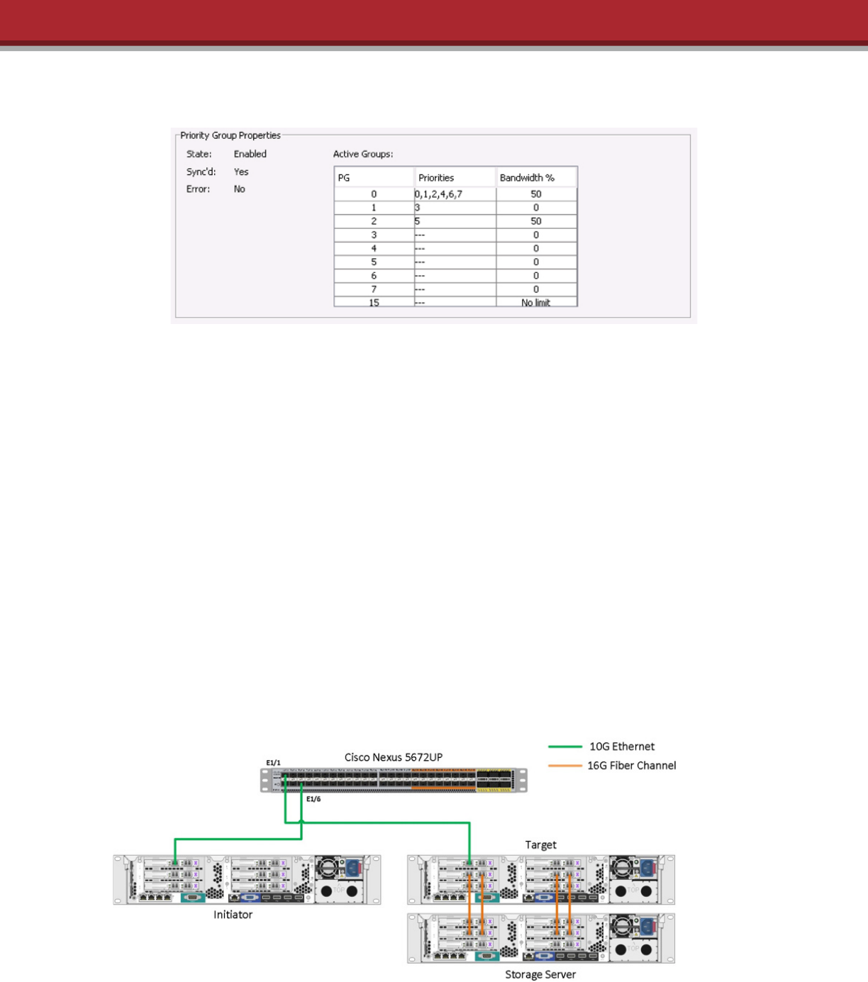
For this evaluation, the network was configured to have trac over a designated VLAN with RoCE transmissions assigned to CoS 5. RoCE trac
was marked as a non-drop class and maximum transfer unit (MTU) values were assigned. As shown in Figure 3, 50% of bandwidth was allocated
to RoCE CoS 5 and the remaining bandwidth was allocated to the default CoS (all other classes of trac except the RoCE class). For trac
marked with COS 3 no bandwidth allocation, that trac is not used in the test.
7 WHITE PAPER | Best Practices for Deployments using DCB and RoCE
DCBX was used to discover peers and exchange configuration information between switches and network adapters. PFC and ETS parameters were
exchanged where network adapters had the same configuration as the switch.
Tests were performed with and without congestion in the network for both topologies. A trac generator was used with test cases that had
congestion. Flows of generated trac were in the default CoS (CoS 0) and the RoCE class (CoS 5). This trac pattern resulted in Per Priority Pause
(PPP) frames in the RoCE CoS.
Tests were performed for this white paper using two topologies.
Topology 1: Stand-alone Nexus 5672UP topology
In the first topology, a Cisco Nexus 5672UP was connected to targets and initiators over 10GbE connections. Tests were performed over the network
with and without congestion, and SMB direct enabled and disabled.
To achieve near line rate performance loads between the initiator and target SMB Direct over RoCE end points a high performance target
configuration was created. The SMB Direct storage server used four storage volumes from a SanBlaze VirtuaLUN which presented flash storage
volumes carried over four 16Gb Fibre Channel (16GFC) links. This configuration ensures that the back end storage devices are overprovisioned in
relation to the 10GbE SMB Direct RoCE connections so as not to be the limiting performance point for these test cases. These volumes are then
partitioned and formatted as NTFS volumes then shared for SMB access. The initiator server then queries the IP address assigned to the target server
SMB Direct port and maps the available four share points. To generate trac and record performance results from the initiator over the SMB Direct
path Medusa Labs test tools was used to perform I/O on the four mapped SMB drives.
Figure 3. PFC and ETS parameters propagated by DCBX and CNA
Figure 4. Topology 1: Cisco Nexus 5672UP stand alone

8 WHITE PAPER | Best Practices for Deployments using DCB and RoCE
Topology 2: Multi-tier topology
A second topology was introduced to see the impact of RoCE on a multi-layer network. The initiators were connected over 10GbE connections to
a Cisco Nexus 2348UPQ fabric extender as a top of rack switch. The Fabric extender was connected over 40GbE connections a Cisco Nexus 5672UP
switch that was used as an end of row switch. The targets were connected with 10GbE connections to a second Cisco Nexus 5672UP that was a top
of rack switch. The end of row switch and top of rack switches were connected to a Cisco Nexus 5624Q aggregation switch.
Figure 5. Topology 2: Cisco Nexus 2348UPQ, Nexus 5672UP and Nexus 5624Q in multitier topology

9 WHITE PAPER | Best Practices for Deployments using DCB and RoCE
RoCE Evaluation Results
Tests were done with the following conditions:
Topology 1: Single-tier
No congestion for RoCE and TCP trac: No PPP frames were transmitted or received and no packets were discarded (as expected).
Figure 6. Topology 1 network under congestion

10 WHITE PAPER | Best Practices for Deployments using DCB and RoCE
To simulate congestion, a trac generator was used. Flows of generated trac are in default class (CoS 0) and in RoCE class (CoS 5). This trac
patterns lead to occurrence of PPP frames in case of congestion in priority class (RoCE class in this testing).
Congestion for TCP trac: No PPP frames were transmitted or received because there was no congestion in the RoCE class. As shown below, there
were 305,698 packets discarded in the default class (CoS 0) for ingress trac. This is the expected result for the Nexus 5672UP which drops ingress
trac when egress ports are congested:
N5672-RoCE# show queuing interface ethernet 1/6
Ethernet1/6 queuing information:
<snip>
qos-group 0
<snip>
Pkts discarded on ingress : 305698
<snip>
Congestion for RoCe trac: As shown below, the initiator switch transmitted PPP frames to insure there were no lost frames for the RoCE CoS:
N5672-RoCE# sh interface priority-ow-control
============================================================
Port Mode Oper(VL bmap) RxPPP TxPPP
============================================================
Ethernet1/1 On On (28) 0 0
Ethernet1/6 On On (28) 0 107947

11 WHITE PAPER | Best Practices for Deployments using DCB and RoCE
Topology 2: Multi-tier
With this topology PFC is enabled on ports connected to adapters and ports that interconnect network devices. When there is congestion, PPP
frames are propagated on a per hop basis from the point of congestion to the sender of trac. The following observations were made:
No congestion for RoCE and TCP trac: No PPP frames were transmitted or received and no packets were discarded (same behavior as Topology 1),
and no drop was seen on the interfaces.
Figure 7. Topology 2: Network under congestion

12 WHITE PAPER | Best Practices for Deployments using DCB and RoCE
Congestion for TCP trac: As shown below, trac drops can be seen on the interface where the initiator is connected:
N5672# show queuing interface ethernet 101/1/1 detail
if_slot 33, idx 0x1f640000
Ethernet101/1/1 queuing information:
<snip>
Queueing:
queue qos-group cos priority bandwidth mtu
--------+------------+--------------+---------+---------+----
ctrl-hi n/a 7 PRI 0 2400
ctrl-lo n/a 7 PRI 0 2400
2 0 0 1 2 4 6 WRR 50 9280
3 1 3 WRR 0 2240
7 5 5 WRR 50 5120
<snip>
Queue Statistics:
queue rx tx ags
------+---------------+---------------+-----
0 0 125 ctrl
1 85 1256 ctrl
2 154754483 341816685 data
3 0 0 data
7 0 195026247 data
Port Statistics:
rx drop rx mcast drop rx error tx drop mux ovow
---------------+---------------+---------------+---------------+--------------
356897 0 0 0 InActive
<snip>

13 WHITE PAPER | Best Practices for Deployments using DCB and RoCE
Figure 8. Bandwidth with Congested SMB Trac
Congestion for RoCE trac: In exchange of RoCE trac between initiator and target, PPP frames are propagated, from the congested target toward
source of trac. Trac is coming from initiator over a 40GbE link, and from trac generator over a 10GbE link, where PFC and ETS are not in use on
trac generator, we can see ETS engaged on the link toward initiator and only PPP frames on link toward trac generator.
N5672-RoCE# sh interface priority-ow-control
============================================================
Port Mode Oper(VL bmap) RxPPP TxPPP
============================================================
Ethernet1/1 On On (28) 0 0
Ethernet1/6 On On (28) 0 0
Ethernet1/7 On On (28) 0 0
Ethernet1/8 On On (28) 0 212537
Interface Ethernet 1/8 is the link that caries trac from trac generator marked with COS 5. There are no drops on the path from target toward
initiator for the RoCE class of trac.
RoCE Evaluation Observations
The following graphs from sample test results show PFC being properly used to manage the network. As shown In Figure 8, TCP and RoCE trac are
not aected when there is no trac congestion. RoCE trac is maintained at the assigned bandwidth allocation with congestion for TCP and
RoCE trac.
No Trac Congestion
Trac Injected on COS 0 and COS 5
PFC set to 50% for COS 5

14 WHITE PAPER | Best Practices for Deployments using DCB and RoCE
Figure 9. Latency with Congested SMB Trac
Figure 9 shows how latency (average response time) is aected by TCP and RoCE congestion. The test results showed a 10 times increase in latency
for TCP trac with an increase of only 2.5 times latency for RoCE trac.
In the performance example above server applications that use RoCE network file storage in a congested data center network can greatly benefit
both in terms of preserving performance as well as ensuring I/O latencies do not increase to the point of aecting the user experience of server
applications. SMB trac running over TCP or even SMB Direct over iWarp (as opposed to RoCE) can suer serious performance congestion issues
that can aect application throughput, transaction rates and response time.
No Trac Congestion
Trac Injected on COS 0 and COS 5
PFC set to 50% for COS 5

15 WHITE PAPER | Best Practices for Deployments using DCB and RoCE
Conclusion
The requirements for enterprise computing are changing. New virtualized workloads, distributed applications and hyperscale infrastructures are driving
the demand for high throughput, low latency and predictable response times.
RoCE is a proven technology that delivers greater application performance and scalability. It also has the native ability to exploit DCB network protocols
to ensure the quality of storage trac under highly variable trac patterns with multiple concurrent types of workloads.
For this white paper, a number of network topologies using SMB Direct for storage trac and TCP for other applications were tested. The results
demonstrated that the RoCE trac priority and bandwidth reservation were preserved under severely congested conditions. End-to-end PFC and ETS
mechanisms were very eective in maintaining the required performance for the storage trac while still enabling other TCP applications to share the
network.
Cisco and Emulex have a long, proven history and great experience with lossless network protocols. End-to-end RoCE solutions oer the ability to
converge multiple protocols and applications for performance, virtualization and storage onto a common infrastructure. Emulex CNAs and network
adapters and Cisco multiprotocol switches deliver a highly scalable, highly robust and very cost eective solution for enterprise customers across a wide
selection of capabilities and price points.
References
• For further information regarding Emulex products that support RoCe
• Detailed instructions for configuring RoCE with SMB Direct using the Emulex OCe14000 adapters
• Detailed instructions for configuring RoCE on Linux operation systems using Emulex OCe14000 adapters
• Cisco Nexus 5600 Platform Switches Data Sheet
• Cisco Nexus 5600 Platform 40-Gbps Switches Data Sheet
• Cisco Nexus 2300 Platform Fabric Extenders Data Sheet

16 WHITE PAPER | Best Practices for Deployments using DCB and RoCE
Appendix A: Switch Configuration Settings
Topology 1 – configuration
*** standalone topology conguration ****
class-map type qos match-all RoCE_qos_class
match cos 5
class-map type queuing RoCE_queuing_class
match qos-group 5
policy-map type qos RoCE_qos_policy
class RoCE_qos_class
set qos-group 5
class class-fcoe
set qos-group 1
policy-map type queuing RoCE_queuing_policy
class type queuing RoCE_queuing_class
bandwidth percent 50
class type queuing class-fcoe
bandwidth percent 0
class type queuing class-default
bandwidth percent 50
class-map type network-qos RoCE_network_class
match qos-group 5
policy-map type network-qos RoCE_network_policy
class type network-qos RoCE_network_class
pause no-drop
mtu 5000
class type network-qos class-fcoe
pause no-drop
mtu 2158
class type network-qos class-default
mtu 9216
system qos
service-policy type qos input RoCE_qos_policy
service-policy type queuing input RoCE_queuing_policy
service-policy type queuing output RoCE_queuing_policy
service-policy type network-qos RoCE_network_policy

17 WHITE PAPER | Best Practices for Deployments using DCB and RoCE
vlan 1, 2000
interface Ethernet1/1
priority-ow-control mode on
switchport mode trunk
switchport trunk allowed vlan 2000
interface Ethernet1/6
priority-ow-control mode on
switchport mode trunk
switchport trunk allowed vlan 2000
interface Ethernet1/7
switchport mode trunk
switchport trunk allowed vlan 2000
interface Ethernet1/8
switchport mode trunk
switchport trunk allowed vlan 2000
interface Ethernet1/9
switchport mode trunk
switchport trunk allowed vlan 2000
interface Ethernet1/10
switchport mode trunk
switchport trunk allowed vlan 2000
Topology 2 - configuration
*** conguration of end of row switch ****
feature lldp
feature fex
class-map type qos match-all RoCE_qos_class

18 WHITE PAPER | Best Practices for Deployments using DCB and RoCE
match cos 5
class-map type queuing RoCE_queuing_class
match qos-group 5
policy-map type qos RoCE_qos_policy
class RoCE_qos_class
set qos-group 5
class class-fcoe
set qos-group 1
policy-map type queuing RoCE_queuing_policy
class type queuing RoCE_queuing_class
bandwidth percent 50
class type queuing class-fcoe
bandwidth percent 0
class type queuing class-default
bandwidth percent 50
class-map type network-qos RoCE_network_class
match qos-group 5
policy-map type network-qos RoCE_network_policy
class type network-qos RoCE_network_class
pause no-drop
mtu 5000
class type network-qos class-fcoe
pause no-drop
mtu 2158
class type network-qos class-default
mtu 9216
system qos
service-policy type qos input RoCE_qos_policy
service-policy type queuing input RoCE_queuing_policy
service-policy type queuing output RoCE_queuing_policy
service-policy type network-qos RoCE_network_policy
fex 101
pinning max-links 1
description “FEX0101”
interface port-channel101
switchport mode fex-fabric

19 WHITE PAPER | Best Practices for Deployments using DCB and RoCE
fex associate 101
interface Ethernet1/1
switchport mode trunk
switchport trunk allowed vlan 2000
interface Ethernet1/2
switchport mode trunk
switchport trunk allowed vlan 2000
interface Ethernet1/3
interface Ethernet1/4
interface Ethernet1/5
switchport mode trunk
switchport trunk allowed vlan 2000
interface Ethernet1/6
switchport mode trunk
switchport trunk allowed vlan 2000
interface Ethernet1/7
switchport mode trunk
switchport trunk allowed vlan 2000
interface Ethernet1/8
switchport mode trunk
switchport trunk allowed vlan 2000
<snip>
interface Ethernet2/1
priority-ow-control mode on
switchport mode trunk
switchport trunk allowed vlan 2000
<snip>

20 WHITE PAPER | Best Practices for Deployments using DCB and RoCE
interface Ethernet2/3
switchport mode fex-fabric
fex associate 101
channel-group 101
<snip>
interface Ethernet101/1/1
priority-ow-control mode on
switchport mode trunk
switchport trunk allowed vlan 2000
owcontrol send off
**** aggregation switch conguration ***
feature telnet
feature lldp
class-map type qos match-all RoCE_qos_class
match cos 5
class-map type queuing RoCE_queuing_class
match qos-group 5
policy-map type qos RoCE_qos_policy
class RoCE_qos_class
set qos-group 5
class class-fcoe
set qos-group 1
policy-map type queuing RoCE_queuing_policy
class type queuing RoCE_queuing_class
bandwidth percent 50
class type queuing class-fcoe
bandwidth percent 0
class type queuing class-default
bandwidth percent 50
class-map type network-qos RoCE_network_class
match qos-group 5
policy-map type network-qos RoCE_network_policy

21 WHITE PAPER | Best Practices for Deployments using DCB and RoCE
class type network-qos RoCE_network_class
pause no-drop
mtu 5000
class type network-qos class-fcoe
pause no-drop
mtu 2158
class type network-qos class-default
mtu 9216
system qos
service-policy type qos input RoCE_qos_policy
service-policy type queuing input RoCE_queuing_policy
service-policy type queuing output RoCE_queuing_policy
service-policy type network-qos RoCE_network_policy
vlan 1, 2000
interface Ethernet1/1
priority-ow-control mode on
switchport mode trunk
switchport trunk allowed vlan 2000
interface Ethernet1/2
priority-ow-control mode on
switchport mode trunk
switchport trunk allowed vlan 2000
*** stand-alone topology conguration ****
class-map type qos match-all RoCE_qos_class
match cos 5
class-map type queuing RoCE_queuing_class
match qos-group 5
policy-map type qos RoCE_qos_policy
class RoCE_qos_class
set qos-group 5
class class-fcoe

22 WHITE PAPER | Best Practices for Deployments using DCB and RoCE
set qos-group 1
policy-map type queuing RoCE_queuing_policy
class type queuing RoCE_queuing_class
bandwidth percent 50
class type queuing class-fcoe
bandwidth percent 0
class type queuing class-default
bandwidth percent 50
class-map type network-qos RoCE_network_class
match qos-group 5
policy-map type network-qos RoCE_network_policy
class type network-qos RoCE_network_class
pause no-drop
mtu 5000
class type network-qos class-fcoe
pause no-drop
mtu 2158
class type network-qos class-default
mtu 9216
system qos
service-policy type qos input RoCE_qos_policy
service-policy type queuing input RoCE_queuing_policy
service-policy type queuing output RoCE_queuing_policy
service-policy type network-qos RoCE_network_policy
vlan 1, 2000
interface Ethernet1/1
priority-ow-control mode on
switchport mode trunk
switchport trunk allowed vlan 2000
interface Ethernet1/6
priority-ow-control mode on
switchport mode trunk
switchport trunk allowed vlan 2000

ELX15-2593· 6/15
Avago, Avago Technologies, Emulex, and the Emulex logo are trademarks of Avago Technologies in the United States and other countries. All other brand and product names are the trademarks of their respective owners. Copyright ©2015 Avago Technologies.
All rights reserved.
For product information and a complete list of distributors, please visit our website at
www.emulex.com
interface Ethernet1/7
switchport mode trunk
switchport trunk allowed vlan 2000
interface Ethernet1/8
switchport mode trunk
switchport trunk allowed vlan 2000
interface Ethernet1/9
switchport mode trunk
switchport trunk allowed vlan 2000
interface Ethernet1/10
switchport mode trunk
switchport trunk allowed vlan 2000
