
Recommendation for Space Data System Standards
BLUE BOOK
PROXIMITY-1 SPACE
LINK PROTOCOL—
PHYSICAL LAYER
RECOMMENDED STANDARD
CCSDS 211.1-B-4
December 2013

Recommendation for Space Data System Standards
PROXIMITY-1 SPACE
LINK PROTOCOL—
PHYSICAL LAYER
RECOMMENDED STANDARD
CCSDS 211.1-B-4
BLUE BOOK
December 2013

CCSDS RECOMMENDED STANDARD FOR PROXIMITY-1 SPACE LINK PROTOCOL—
PHYSICAL LAYER
CCSDS 211.1-B-4 Page 1-1 December 2013
AUTHORITY
Issue: Recommended Standard, Issue 4
Date: December 2013
Location: Washington, DC, USA
This document has been approved for publication by the Management Council of the
Consultative Committee for Space Data Systems (CCSDS) and represents the consensus
technical agreement of the participating CCSDS Member Agencies. The procedure for
review and authorization of CCSDS documents is detailed in Organization and Processes for
the Consultative Committee for Space Data Systems (CCSDS A02.1-Y-3), and the record of
Agency participation in the authorization of this document can be obtained from the CCSDS
Secretariat at the address below.
This document is published and maintained by:
CCSDS Secretariat
Space Communications and Navigation Office, 7L70
Space Operations Mission Directorate
NASA Headquarters
Washington, DC 20546-0001, USA
CCSDS RECOMMENDED STANDARD FOR PROXIMITY-1 SPACE LINK PROTOCOL—
PHYSICAL LAYER
CCSDS 211.1-B-4 Page 1-2 December 2013
STATEMENT OF INTENT
The Consultative Committee for Space Data Systems (CCSDS) is an organization officially
established by the management of its members. The Committee meets periodically to address
data systems problems that are common to all participants, and to formulate sound technical
solutions to these problems. Inasmuch as participation in the CCSDS is completely
voluntary, the results of Committee actions are termed Recommended Standards and are
not considered binding on any Agency.
This Recommended Standard is issued by, and represents the consensus of, the CCSDS
members. Endorsement of this Recommendation is entirely voluntary. Endorsement,
however, indicates the following understandings:
o Whenever a member establishes a CCSDS-related standard, this standard will be in
accord with the relevant Recommended Standard. Establishing such a standard
does not preclude other provisions which a member may develop.
o Whenever a member establishes a CCSDS-related standard, that member will
provide other CCSDS members with the following information:
-- The standard itself.
-- The anticipated date of initial operational capability.
-- The anticipated duration of operational service.
o Specific service arrangements shall be made via memoranda of agreement. Neither
this Recommended Standard nor any ensuing standard is a substitute for a
memorandum of agreement.
No later than three years from its date of issuance, this Recommended Standard will be
reviewed by the CCSDS to determine whether it should: (1) remain in effect without change;
(2) be changed to reflect the impact of new technologies, new requirements, or new
directions; or (3) be retired or canceled.
In those instances when a new version of a Recommended Standard is issued, existing
CCSDS-related member standards and implementations are not negated or deemed to be
non-CCSDS compatible. It is the responsibility of each member to determine when such
standards or implementations are to be modified. Each member is, however, strongly
encouraged to direct planning for its new standards and implementations towards the later
version of the Recommended Standard.
CCSDS RECOMMENDED STANDARD FOR PROXIMITY-1 SPACE LINK PROTOCOL—
PHYSICAL LAYER
CCSDS 211.1-B-4 Page 1-3 December 2013
FOREWORD
Attention is drawn to the possibility that some of the elements of this document may be the
subject of patent rights. CCSDS shall not be held responsible for identifying any or all such
patent rights.
Through the process of normal evolution, it is expected that expansion, deletion, or
modification of this document may occur. This Recommended Standard is therefore subject
to CCSDS document management and change control procedures, which are defined in
Organization and Processes for the Consultative Committee for Space Data Systems
(CCSDS A02.1-Y-3). Current versions of CCSDS documents are maintained at the CCSDS
Web site:
http://www.ccsds.org/
Questions relating to the contents or status of this document should be addressed to the
CCSDS Secretariat at the address indicated on page i.

CCSDS RECOMMENDED STANDARD FOR PROXIMITY-1 SPACE LINK PROTOCOL—
PHYSICAL LAYER
CCSDS 211.1-B-4 Page 1-4 December 2013
At time of publication, the active Member and Observer Agencies of the CCSDS were:
Member Agencies
– Agenzia Spaziale Italiana (ASI)/Italy.
– Canadian Space Agency (CSA)/Canada.
– Centre National d’Etudes Spatiales (CNES)/France.
– China National Space Administration (CNSA)/People’s Republic of China.
– Deutsches Zentrum für Luft- und Raumfahrt (DLR)/Germany.
– European Space Agency (ESA)/Europe.
– Federal Space Agency (FSA)/Russian Federation.
– Instituto Nacional de Pesquisas Espaciais (INPE)/Brazil.
– Japan Aerospace Exploration Agency (JAXA)/Japan.
– National Aeronautics and Space Administration (NASA)/USA.
– UK Space Agency/United Kingdom.
Observer Agencies
– Austrian Space Agency (ASA)/Austria.
– Belgian Federal Science Policy Office (BFSPO)/Belgium.
– Central Research Institute of Machine Building (TsNIIMash)/Russian Federation.
– China Satellite Launch and Tracking Control General, Beijing Institute of Tracking
and Telecommunications Technology (CLTC/BITTT)/China.
– Chinese Academy of Sciences (CAS)/China.
– Chinese Academy of Space Technology (CAST)/China.
– Commonwealth Scientific and Industrial Research Organization (CSIRO)/Australia.
– Danish National Space Center (DNSC)/Denmark.
– Departamento de Ciência e Tecnologia Aeroespacial (DCTA)/Brazil.
– European Organization for the Exploitation of Meteorological Satellites
(EUMETSAT)/Europe.
– European Telecommunications Satellite Organization (EUTELSAT)/Europe.
– Geo-Informatics and Space Technology Development Agency (GISTDA)/Thailand.
– Hellenic National Space Committee (HNSC)/Greece.
– Indian Space Research Organization (ISRO)/India.
– Institute of Space Research (IKI)/Russian Federation.
– KFKI Research Institute for Particle & Nuclear Physics (KFKI)/Hungary.
– Korea Aerospace Research Institute (KARI)/Korea.
– Ministry of Communications (MOC)/Israel.
– National Institute of Information and Communications Technology (NICT)/Japan.
– National Oceanic and Atmospheric Administration (NOAA)/USA.
– National Space Agency of the Republic of Kazakhstan (NSARK)/Kazakhstan.
– National Space Organization (NSPO)/Chinese Taipei.
– Naval Center for Space Technology (NCST)/USA.
– Scientific and Technological Research Council of Turkey (TUBITAK)/Turkey.
– South African National Space Agency (SANSA)/Republic of South Africa.
– Space and Upper Atmosphere Research Commission (SUPARCO)/Pakistan.
– Swedish Space Corporation (SSC)/Sweden.
– Swiss Space Office (SSO)/Switzerland.
– United States Geological Survey (USGS)/USA.
CCSDS RECOMMENDED STANDARD FOR PROXIMITY-1 SPACE LINK PROTOCOL—
PHYSICAL LAYER
CCSDS 211.1-B-4 Page 1-5 December 2013
DOCUMENT CONTROL
Document Title Date Status
CCSDS
211.0-B-1
Proximity-1 Space Link Protocol October
2002
Original issue,
superseded
CCSDS
211.1-B-1
Proximity-1 Space Link Protocol—
Physical Layer
April
2003
Superseded
CCSDS
211.1-B-2
Proximity-1 Space Link Protocol—
Physical Layer
May
2004
Superseded
CCSDS
211.1-B-3
Proximity-1 Space Link Protocol—
Physical Layer, Recommended
Standard, Issue 3
March
2006
Superseded
CCSDS
211.1-B-4
Proximity-1 Space Link Protocol—
Physical Layer, Recommended
Standard, Issue 4
December
2013
Current issue:
This update includes
several improvements
and clarifications,
accomplishing better
alignment and
consistency with the
other Proximity-1 Blue
Books.
CCSDS
211.1-B-4
EC 1
Editorial change 1 January
2018
Repairs broken cross
reference; improves
formatting in Table of
Contents.
NOTE – Changes from the current issue are too extensive to permit markup.

CCSDS RECOMMENDED STANDARD FOR PROXIMITY-1 SPACE LINK PROTOCOL—
PHYSICAL LAYER
CCSDS 211.1-B-4 Page 1-6 December 2013
CONTENTS
Section Page
1 INTRODUCTION .......................................................................................................... 1-1
1.1 PURPOSE ............................................................................................................... 1-1
1.2 SCOPE .................................................................................................................... 1-1
1.3 APPLICABILITY ................................................................................................... 1-1
1.4 RATIONALE .......................................................................................................... 1-2
1.5 CONVENTIONS AND DEFINITIONS................................................................. 1-2
1.6 REFERENCES ....................................................................................................... 1-5
2 OVERVIEW ................................................................................................................... 2-1
2.1 PHYSICAL LAYER OVERVIEW ........................................................................ 2-1
2.2 DATA LINK LAYER OVERVIEW ...................................................................... 2-1
3 GENERAL REQUIREMENTS FOR THE PHYSICAL LAYER ............................ 3-1
3.1 RADIO EQUIPMENT ............................................................................................ 3-1
3.2 PHYSICAL LAYER FUNCTIONS ....................................................................... 3-1
3.3 CONTROLLED COMMUNICATIONS CHANNEL PROPERTIES ................... 3-5
3.4 PERFORMANCE REQUIREMENTS ................................................................... 3-9
ANNEX A PROTOCOL IMPLEMENTATION CONFORMANCE
STATEMENT PROFORMA (NORMATIVE) .......................................... A-1
ANNEX B SECURITY, SANA, AND PATENT CONSIDERATIONS
(INFORMATIVE) ..........................................................................................B-1
ANNEX C INFORMATIVE REFERENCES (INFORMATIVE) .............................. C-1
ANNEX D ABBREVIATIONS AND ACRONYMS (INFORMATIVE) .................... D-1
Figure
1-1 Proximity-1 Rate Terminology ..................................................................................... 1-5
2-1 Sim
plified Overview of Proximity-1 Layers ................................................................ 2-2
3-1 Control Variables, Signals, and Data Transfers ............................................................ 3-2
3-2 Oscillator Phase Noise
................................................................................................ 3-10
3-3 Discrete Lines Tem
plate for the Transmitter (Normalized Power in
dBc vs. Normalized Frequency: (f-f
c
)/A) .................................................................. 3-10

CCSDS RECOMMENDED STANDARD FOR PROXIMITY-1 SPACE LINK PROTOCOL—
PHYSICAL LAYER
CCSDS 211.1-B-4 Page 1-7 December 2013
CONTENTS (continued)
Table Page
3-1 Categories of Radio Equipment Contained on Proximity-1 Link Elements ................. 3-1
3-2 Control Variables for Transmitter ................................................................................ 3-3
3-3 Control Variables for Receiver ..................................................................................... 3-4
3-4 Proximity-1 Channel Assignments 0 through 7 (Frequencies in MHz) ....................... 3-7
A-1 Major Capabilities ....................................................................................................... A-4
CCSDS RECOMMENDED STANDARD FOR PROXIMITY-1 SPACE LINK PROTOCOL—
PHYSICAL LAYER
CCSDS 211.1-B-4 Page 1-1 December 2013
1 INTRODUCTION
1.1 PURPOSE
The purpose of this Recommended Standard is to specify Physical Layer procedures used
with the Proximity-1 Data Link Layer (references [3] and [2]). Proximity space links are
defined to be short-range, bi-directional, fixed or mobile radio links, generally used to
communicate among probes, landers, rovers, orbiting constellations, and orbiting relays.
These links are characterized by short time delays, moderate (not weak) signals, and short,
independent sessions.
1.2 SCOPE
This Recommended Standard defines the Proximity-1 Space Link Protocol Physical Layer.
The specification for the channel connection process, provision for frequency bands and
assignments, hailing channel, polarization, modulation, data rates, and performance
requirements are defined in this document.
Currently, the Physical Layer only defines operations at UHF frequencies for the Mars
environment.
The Data Link Layer is defined in the two separate CCSDS Recommended Standards entitled,
Proximity-1 Space Link Protocol—Coding and Synchronization Sublayer (reference [2]), and
Proximity-1 Space Link Protocol—Data Link Layer (reference [3]).
This Recommended Standard does not specify
a) individual implementations or products;
b) implementation of service interfaces within real systems;
c) the methods or technologies required to perform the procedures; or
d) the management activities required to configure and control the protocol.
1.3 APPLICABILITY
This Recom
mended Standard applies to the creation of Agency standards and to future data
communications over space links between CCSDS Agencies in cross-support situations. It
applies also to internal Agency links where no cross-support is required. It includes
specification of the services and protocols for inter-Agency cross support. It is neither a
specification of, nor a design for, systems that may be implemented for existing or future
missions.
The Recommended Standard specified in this document is to be invoked through the normal
standards programs of each CCSDS Agency and is applicable to those missions for which
cross support based on capabilities described in this Recommended Standard is anticipated.
Where mandatory capabilities are clearly indicated in sections of the Recommended
CCSDS RECOMMENDED STANDARD FOR PROXIMITY-1 SPACE LINK PROTOCOL—
PHYSICAL LAYER
CCSDS 211.1-B-4 Page 1-2 December 2013
Standard, they must be implemented when this document is used as a basis for cross support.
Where options are allowed or implied, implementation of these options is subject to specific
bilateral cross support agreements between the Agencies involved.
1.4 RATIONALE
The CCSDS believes it is important to document the rationale underlying the
recommendations chosen, so that future evaluations of proposed changes or improvements
will not lose sight of previous decisions. Concept and rationale behind the decisions that
formed the basis for Proximity-1 are documented in the CCSDS Proximity-1 Space Link
Protocol Green Book, reference [C1].
1.5 CONVENTIONS AND DEFINITIONS
1.5.1 DEFINITIONS
1.5.1.1 Terms from the Open Systems Interconnection (OSI) Basic Reference Model
This Recommended Standard makes use of a number of terms defined in reference [1]. In
this Recommended Standard those terms are used in a generic sense, i.e., in the sense that
those terms are generally applicable to any of a variety of technologies that provide for the
exchange of information between real systems. Those terms are as follows:
a) connection;
b) Data Link Layer;
c) Physical Layer;
d) protocol data unit;
e) real system;
f) service;
g) service data unit.
1.5.1.2 Terms Defined in This Recommended Standard
For the purposes of this Recommended Standard, the following definitions also apply. Many
other terms that pertain to specific items are defined in the appropriate sections.
caller and responder: Initiator and receiver, respectively, in a Proximity space link session.
CCSDS RECOMMENDED STANDARD FOR PROXIMITY-1 SPACE LINK PROTOCOL—
PHYSICAL LAYER
CCSDS 211.1-B-4 Page 1-3 December 2013
NOTE – A caller transceiver is the initiator of the link establishment process and
manager of negotiation (if required) of the session. A responder transceiver
typically receives link establishment parameters from the caller. The caller
initiates communication between itself and a responder on a prearranged
communications channel with predefined controlling parameters. As necessary,
the caller and responder may negotiate the controlling parameters for the session
(at some level between fully controlled and completely adaptive).
forward link: That portion of a Proximity space link in which the caller transmits and the
responder receives (typically a command link). The term ‘forward’ is used in
association with any parameters referring to the forward link.
hailing: The persistent activity used to establish a Proximity link by a caller to a responder
in either full or half duplex. It does not apply to simplex operations.
hailing channel: The forward and return frequency pairs that a caller and responder use to
establish physical link communications.
physical channel: The RF channel upon which the stream of channel symbols is transferred
over a space link in a single direction.
PLTU: Proximity Link Transmission Unit, the data unit composed of the Attached
Synchronization Marker, the Version-3 Transfer Frame, and the attached Cyclic
Redundancy Check (CRC)-32.
Proximity link: A full-duplex, half-duplex, or simplex link for the transfer of data between
Proximity-1 entities in a session.
return link: That portion of a Proximity space link in which the responder transmits and the
caller receives (typically a telemetry link). The term ‘return’ is used in association
with any parameters referring to the return link.
session: A dialog between two or more communicating Proximity link transceivers.
NOTE – A session consists of three distinct operational phases: session establishment,
data services (which may include resynchronization and/or reconnect subphases),
and session termination. Session termination can be coordinated (through the
exchange of no-more-data-to-send directives), or, if communication is lost
(inability to resynchronize or reconnect), the transceivers will eventually
independently conclude the dialog is over.
space link: A communications link between transmitting and receiving entities, at least one of
which is in space.
working channel: A forward and return frequency pair used for transferring User
data/information frames (U-frames) and Protocol/supervisory frames (P-frames)
during the data service and session termination phases.
CCSDS RECOMMENDED STANDARD FOR PROXIMITY-1 SPACE LINK PROTOCOL—
PHYSICAL LAYER
CCSDS 211.1-B-4 Page 1-4 December 2013
1.5.2 NOMENCLATURE
1.5.2.1 NORMATIVE TEXT
The following conventions apply for the normative specifications in this Recommended
Standard:
a) the words ‘shall’ and ‘must’ imply a binding and verifiable specification;
b) the word ‘should’ implies an optional, but desirable, specification;
c) the word ‘may’ implies an optional specification;
d) the words ‘is’, ‘are’, and ‘will’ imply statements of fact.
NOTE – These conventions do not imply constraints on diction in text that is clearly
informative in nature.
1.5.2.2 INFORMATIVE TEXT
In the normative section of this document (section 3), informative text is set off from the
normative specifications either in notes or under one of the following subsection headings:
– Overview;
– Background;
– Rationale;
– Discussion.
1.5.3 CONVENTIONS
Throughout this Recommended Standard, directive, parameter, variable, and signal names
are presented with all upper-case characters; data-field and MIB-parameter names are
presented with initial capitalization; values and state names are presented with predominantly
lowercase italic characters.
In Proximity-1, data rate (R
d
), coded symbol rate (R
cs
) and channel symbol rate (R
chs
) are
used to denote respectively:
– the data rate of the bitstream composed by PLTUs and Idle data measured at the
encoder input;
– the coded data rate measured at the interface between the Coding and
Synchronization Sublayer and the Physical Layer; and
– the rate measured at the output of the transmitter.
CCSDS RECOMMENDED STANDARD FOR PROXIMITY-1 SPACE LINK PROTOCOL—
PHYSICAL LAYER
CCSDS 211.1-B-4 Page 1-5 December 2013
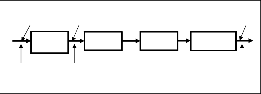
The terms are used as shown in figure 1-1.
Bi-Phase-L
RF
MODULATOR
CHANNELBITSTREAM
FOR ENCODING
SYMBOLS
POWER AMPLIFIER
& RF CHAIN
CHANNEL
SYMBOL RATE
REFERENCE
POINT
(R
chs
)
CODED SYMBOL RATE
CODED
SYMBOLS
REFERENCE POINT
(R
cs
)
ENCODER
(or Bypass)
DATA RATE
REFERENCE POINT
(R
d
)
Figure 1-1: Proximity-1 Rate Terminology
With respect to the modulation scheme specified in 3.3.5.1, the following relationship applies
for the purpose of the present standard:
R
chs
= R
cs
1.6 REFERENCES
The following publications contain provisions which, through reference in this text,
constitute provisions of this document. At the time of publication, the editions indicated
were valid. All publications are subject to revision, and users of this document are
encouraged to investigate the possibility of applying the most recent editions of the
publications indicated below. The CCSDS Secretariat maintains a register of currently valid
CCSDS publications.
[1] Information Technology—Open Systems Interconnection—Basic Reference Model: The
Basic Model. International Standard, ISO/IEC 7498-1:1994. 2nd ed. Geneva: ISO,
1994.
[2] Proximity-1 Space Link Protocol—Coding and Synchronization Sublayer. Issue 2.
Recommendation for Space Data System Standards (Blue Book), CCSDS 211.2-B-2.
Washington, D.C.: CCSDS, December 2013.
[3] Proximity-1 Space Link Protocol—Data Link Layer. Issue 5. Recommendation for
Space Data System Standards (Blue Book), CCSDS 211.0-B-5. Washington, D.C.:
CCSDS, December 2013.
CCSDS RECOMMENDED STANDARD FOR PROXIMITY-1 SPACE LINK PROTOCOL—
PHYSICAL LAYER
CCSDS 211.1-B-4 Page 2-1 December 2013
2 OVERVIEW
2.1 PHYSICAL LAYER OVERVIEW
Proximity-1 is a bi-directional Space Link Layer protocol for use by space missions. It
consists of a Physical Layer (the subject of this document) and a Data Link Layer (references
[2] and [3]). This protocol has been designed to meet the requirements of space missions for
efficient transfer of space data over various types and characteristics of Proximity space
links.
Proximity-1 activities are divided between a send side and a receive side. The send side is
concerned with the transmitted physical channel, and also with the acquisition of the received
physical channel in order to establish a Proximity-1 link. The operation of the transmitter is
state-driven. The receive side is concerned with the reception of data on the received
physical channel: the input symbols stream and the protocol data units it contains. Once the
receiver is turned on, its operation is modeless. It accepts and processes all valid local and
remote directives and received service data units.
On the send side, the Physical Layer:
– accepts control variables from the MAC Sublayer of the Data Link Layer for control
of the transceiver;
– accepts a coded symbols stream from the Coding & Synchronization Sublayer
(reference [2]) of the Data Link Layer for modulation onto the radiated carrier.
On the receive side, the Physical Layer:
– provides status signals (CARRIER_ACQUIRED and SYMBOL_INLOCK_STATUS)
to the MAC Sublayer of the Data Link Layer.
2.2 DATA LINK LAYER OVERVIEW
This subsection provides a brief overview of the Data Link Layer, with em
phasis on the
features relevant to the Physical Layer. For a fuller description of the overall Proximity-1
system, of the Data Link Layer and of its sublayers (see reference [3]).
On the send side, the Data Link Layer is responsible for providing the coded symbols to be
transmitted by the Physical Layer. On the receive side, the Data Link Layer accepts the
serial coded symbols stream output from the receiver in the Physical Layer and processes the
Protocol Data Units contained in it.
Within the Data Link Layer, the Medium Access Control (MAC) Sublayer (reference [3])
and the Coding and Synchronization (C&S) Sublayer (reference [2]) have interfaces to the
Physical Layer.

CCSDS RECOMMENDED STANDARD FOR PROXIMITY-1 SPACE LINK PROTOCOL—
PHYSICAL LAYER
CCSDS 211.1-B-4 Page 2-2 December 2013
The Medium Access Control (MAC) Sublayer controls the establishment, maintenance, and
termination of communications sessions for point-to-point communications between
Proximity entities. It controls the operational state of the Data Link and Physical Layers,
using control variables. It accepts Proximity-1 directives both from the local vehicle
controller and across the Proximity link to control its operations. The MAC Sublayer is also
responsible for the storage and distribution of the Management Information Base (MIB)
parameters.
On the send side, the C&S Sublayer generates the output coded symbols stream, containing
Proximity Link Transmission Units (PLTUs) and Idle data, which is delivered to the Physical
Layer for modulation onto the radiated carrier. On the receive side, the C&S Sublayer
accepts the incoming serial coded symbols stream from the Physical Layer and delimits each
PLTU contained in the symbol stream.
Figure 2-1 gives a simplified view of the relationship of the Data Link Layer to the Physical
Layer. (For a more detailed view of the Proximity-1 system, see reference [3].)
Physical Layer
Frame Sublayer
Data Services
Sublayer
I/O Sublayer
MAC
Sublayer
(MIB)
Local S/C
Controller
INPUT of USER DATA
+ Routing information
USER DATA
Delivery
SEND RECEIVE
Data Link Layer
Coding & Synchronization Layer
Figure 2-1: Simplified Overview of Proximity-1 Layers

CCSDS RECOMMENDED STANDARD FOR PROXIMITY-1 SPACE LINK PROTOCOL—
PHYSICAL LAYER
CCSDS 211.1-B-4 Page 3-1 December 2013
3 GENERAL REQUIREMENTS FOR THE PHYSICAL LAYER
3.1 RADIO EQUIPMENT
3.1.1 OVERVIEW
The Proximity-1 Link system supports the communication and navigation needs between a
variety of network elements, e.g., orbiters, landers, rovers, microprobes, balloons, aerobots,
gliders. The categories of radio equipment in network elements (E1, E2,…) are listed in
table 3-1.
3.1.2 COHERENCY REQUIREMENT
Link elements in category E2c (table 3-1), for which range and range-rate measurements are
needed, shall have transmit/receive frequency coherency capability. (See 3.4.5 for Doppler
tracking and acquisition requirements.)
Table 3-1: Categories of Radio Equipment Contained on Proximity-1 Link Elements
Category Description
E1: Elements with transmit-only capability.
E2: Elements with transmit and receive capability.
E2n: E2 elements with non-coherent mode only.
E2c: E2 elements offering in addition transmit/receive frequency coherency
capability.
E2d: E2 elements with a descoped receiver capable of receiving an FSK modulated
carrier. These elements transmit using PSK modulation.
NOTE – E2d radio equipment is intended to be used in microprobes. This option is not
required for cross support.
3.2 PHYSICAL LAYER FUNCTIONS
3.2.1 OVERVIEW
3.2.1.1 Physical Layer to Data Link Layer Interfaces
The prime function of the Physical Layer is to establish and maintain a communications
channel upon which the data can flow. To enable a physical channel connection, the
Physical Layer goes through a series of actions to establish a communications channel.

CCSDS RECOMMENDED STANDARD FOR PROXIMITY-1 SPACE LINK PROTOCOL—
PHYSICAL LAYER
CCSDS 211.1-B-4 Page 3-2 December 2013
The Physical Layer accepts control variables (MODE, DUPLEX, TRANSMIT,
MODULATION) from the MAC Sublayer of the Data Link Layer for control of the
transceiver. Reference [3] contains the specification of the actions to establish, maintain and
terminate a Proximity-1 communications session: the actions are specified in state tables and
the control variables are defined. Requirements in 3.2.2 and 3.2.3, below, complement the
specifications in reference [3].
Figure 3-1 shows the data and control flows between the Physical Layer and elements of the
Data Link Layer.
MAC sublayer
variables
MODE
DUPLEX
TRANSMIT
MODULATION
coded symbol
stream for
transmission
C&S
Physical layer
Data Link layer
signals:
CARRIER_ACQUIRED
SYMBOL_INLOCK_STATUS
received
coded symbol stream
Figure 3-1: Control Variables, Signals, and Data Transfers
3.2.1.2 Configuration of the Physical Layer
The establishment of the communications channel depends on the configuration of the
following Physical Layer parameters: frequency, polarization, modulation, acquisition, idle
sequence, and coded symbol rates, such that common operating characteristics exist in both
communicating entities.
The MAC Sublayer sets the local transceiver to the desired physical configuration, under the
control of the directives SET TRANSMITTER PARAMETERS and SET RECEIVER
PARAMETERS
. A SET PL EXTENSIONS directive is the mechanism by which additional
Physical Layer parameters defined outside of the Proximity-1 Physical Layer can be enabled
or disabled. The format and content of these and other Proximity-1 directives are specified
in an annex of reference [3].

CCSDS RECOMMENDED STANDARD FOR PROXIMITY-1 SPACE LINK PROTOCOL—
PHYSICAL LAYER
CCSDS 211.1-B-4 Page 3-3 December 2013
3.2.2 TRANSMITTER
3.2.2.1 Operational State of the Transmitter
The operational state of the transmitter shall depend on the state control variables MODE,
TRANSMIT, and MODULATION, as shown in table 3-2.
Table 3-2: Control Variables for Transmitter
MODE TRANSMIT MODULATION Transmitter state
inactive
N/A N/A
off
any value
except
inactive
off
N/A
off
on false
on, radiated output is carrier only
on true
on, data modulated onto the radiated carrier
NOTES
1 Unless MODE is inactive, a change in the value of TRANSMIT signals the Physical
Layer to transition the transmitter to on or off.
2 An MIB parameter, Carrier_Only_Duration, is used in the Data Link Layer to control
the duration of the carrier-only transmission (TRANSMIT = on and MODULATION
= false).
3 When TRANSMIT is on and MODULATION is true, the Physical Layer receives
coded symbols for transmission from the Data Link Layer (C&S Sublayer). The
content of the output coded symbols stream is specified in reference [3], which
defines an output coded sym
bols stream FIFO. The data include PLTUs and Idle
data, for example in the Acquisition sequence that is sent when transmission
commences so that the receiving unit can acquire the signal. The format of Idle data
is specified in reference [2].
3.2.3 RECEIVER
3.2.3.1 Operational State of the Receiver
The operational state of the receiver shall depend on the state control variables MODE,
DUPLEX, and TRANSMIT, as shown in table 3-3.

CCSDS RECOMMENDED STANDARD FOR PROXIMITY-1 SPACE LINK PROTOCOL—
PHYSICAL LAYER
CCSDS 211.1-B-4 Page 3-4 December 2013
Table 3-3: Control Variables for Receiver
MODE DUPLEX TRANSMIT Receiver state
inactive
N/A N/A
off
any value except
inactive
full or
simplex receive
N/A
on
simplex transmit
N/A
off
half on off
half off on
NOTE – The Physical Layer notifies the Data Link Layer (MAC Sublayer) of the status of
the received channel, using the signals CARRIER_ACQUIRED and
SYMBOL_INLOCK_STATUS. When SYMBOL_INLOCK_STATUS is true,
the
Physical Layer delivers the received coded symbol streams to the Data Link
Layer (C&S Sublayer).
3.2.3.2 Acquisition
The receiver shall sweep the frequency channel to which it is assigned in order to acquire
carrier lock at an assigned frequency channel.
NOTE – During this process, the receiver first attempts to lock to the carrier.
3.2.3.3
CARRIER_ACQUIRED signal
3.2.3.3.1 The
CARRIER_ACQUIRED signal shall notify the MAC Sublayer that the receiver
has acquired a carrier signal.
3.2.3.3.2 The CARRIER_ACQUIRED signal shall be set to true when the receiver is locked
to the received RF signal and false when not in lock.
3.2.3.4 SYMBOL_INLOCK_STATUS signal
3.2.3.4.1 The
SYMBOL_INLOCK_STATUS signal shall notify the MAC Sublayer that
symbol synchronization has been acquired and the received serial symbol stream is being
provided to the Data Link Layer.
3.2.3.4.2 The
SYMBOL_INLOCK_STATUS signal shall be set to true when the receiver is in
symbol lock and false when the receiver is not in symbol lock.
CCSDS RECOMMENDED STANDARD FOR PROXIMITY-1 SPACE LINK PROTOCOL—
PHYSICAL LAYER
CCSDS 211.1-B-4 Page 3-5 December 2013
NOTE – The receiver is considered to be in symbol lock when it is confident that its
symbol detection processes are synchronized to the modulated symbol stream
and the symbols output are of an acceptable quality for processing by the Data
Link Layer.
3.2.3.5 Received Symbol Stream
When SYMBOL_INLOCK_STATUS is true, the Physical Layer shall deliver the received
symbol stream to the C&S Sublayer.
NOTE – Soft symbol decisions with at least three bits quantization are recommended
whenever constraints (such as complexity of demodulator) permit.
3.3 CONTROLLED COMMUNICATIONS CHANNEL PROPERTIES
3.3.1 BACKGROUND
This Recommended Standard is designed primarily for use in a Proximity link space
environment far from Earth. The radio frequencies selected in this Recommended Standard
are designed not to cause interference to radio communication services allocated by the
Radio Regulations of the International Telecommunication Union (ITU). It should be noted
that particular precautions have to be taken to protect frequency bands allocated to Near
Earth Space Research, Deep Space, and Space Research, passive.
The frequencies specified near 430 MHz cannot be used for this purpose in the vicinity of the
Earth, and particular precautions have to be taken for equipment testing on Earth. However,
by layering appropriately, provision is made to change only the Physical Layer by adding
other frequencies to enable the same protocol to be used in near Earth applications; in the
latter case a strict compliance with the frequency allocations in the ITU Radio Regulations is
mandatory.
3.3.2 UHF FREQUENCIES
3.3.2.1 General
The frequency range for the UHF Proximity-1 links consists of 60 MHz between 390 MHz to
450 MHz with a 30 MHz guard-band between forward and return frequency bands.
3.3.2.2 Frequency Range
3.3.2.2.1 The forward frequency band shall be from 435 to 450 MHz.
3.3.2.2.2 The return frequency band shall be from 390 to 405 MHz.
CCSDS RECOMMENDED STANDARD FOR PROXIMITY-1 SPACE LINK PROTOCOL—
PHYSICAL LAYER
CCSDS 211.1-B-4 Page 3-6 December 2013
NOTES
1 Annex A of reference [3] defines the SET TRANSMITTER PARAMETERS and SET
RECEIVER PARAMETERS
directives, which are used to configure the channel
assignment for the remote vehicle’s transmitter and receiver for Channels 0 through 7.
Annex A of reference [3] also defines the SET PL EXTENSIONS directive for
Channels 8 through 15.
2 The selection of the frequencies is subject to Space Frequency Coordination Group
(SFCG) recommendations.
3.3.2.3 Hailing Channel
3.3.2.3.1 For interoperability at UHF, the default hailing channel shall be Channel 1
configured for 435.6 MHz in the forward link and 404.4 MHz in the return link (1348/44*33
turnaround ratio).
NOTE – Enterprise-specific hailing channel frequencies can be defined in the default
configuration of the Physical Layer parameters.
3.3.2.3.2 If the Proximity link radio equipment supports only a single channel (i.e., a single
forward and return frequency pair), then the hailing channel shall be the same as the working
channel (see 1.5.1.2).
3.3.2.3.3 If the Proximity link radio equipment supports multiple channels, then the hailing
channel shall be distinct from the working channel.
3.3.2.3.4 After link establishment through hailing is accomplished, transition to the
working channel (if available) should be done as soon as possible.
NOTES
1 Hailing is an activity used to establish a Proximity link with a remote vehicle.
Hailing requires the use of a hailing frequency pair.
2 Hailing is bi-directional; i.e., either element can initiate hailing. Hailing is done at a
low data rate and therefore is a low bandwidth activity. Channel 1 has been selected
to minimize the use of UHF bandwidth.
3 Hailing is performed between transceivers that are pre-configured. Therefore it is
nominally performed on the hailing channel. However, if transceivers are compatibly
configured, hailing can occur on an agreed-to channel. The first generation
transceivers are fixed frequency and use Channel 0.
4 Subsection 4.2 of reference [3] (MAC Sublayer) provides further details on hailing in
the link establishm
ent process. There are various parameters associated with the
hailing activity that are defined in the MIB. Annex B of reference [3] defines these
enterprise-specific param
eters.

CCSDS RECOMMENDED STANDARD FOR PROXIMITY-1 SPACE LINK PROTOCOL—
PHYSICAL LAYER
CCSDS 211.1-B-4 Page 3-7 December 2013
3.3.2.4 Single Forward and Single Return Frequency Pairs
NOTE – Forward and return link frequencies may be coherently related or non-coherent.
3.3.2.4.1 The following three additional channels (fixed single forward and return
frequency pairs) are defined for Proximity-1 operations:
a) Channel 0. In the case where the system requires only one return frequency,
associated with the forward 437.1 MHz frequency, the return frequency shall be
401.585625 MHz (147/160 turnaround ratio).
b) Channel 2. In the case where the system requires only one return frequency,
associated with the forward 439.2 MHz frequency, the return frequency shall be
397.5 MHz (1325/24*61 turnaround ratio).
c) Channel 3. In the case where the system requires only one return frequency,
associated with the forward 444.6 MHz frequency, the return frequency shall be
393.9 MHz (1313/38*39 turnaround ratio).
3.3.2.4.2 Table 3-4 details Proximity-1 channel assignments 0 through 7.
NOTE – Channels 8 through 15 are defined in the SET PL EXTENSIONS directive (see
annex A of reference [3]). The assignment of specific frequencies to these
channels is reserved by CCSDS.
Table 3-4: Proximity-1 Channel Assignments 0 through 7 (Frequencies in MHz)
Channel (Ch) Number Forward (F) Frequency Return (R)Frequency
0 437.1 401.585625
1 435.6 404.4
2 439.2 397.5
3 444.6 393.9
4 Within 435 to 450 Within 390 to 405
5 Within 435 to 450 Within 390 to 405
6 Within 435 to 450 Within 390 to 405
7 Within 435 to 450 Within 390 to 405
3.3.2.5 Multiple Forward and Multiple Return Frequencies
In the case where there is a need for one or multiple return frequencies paired with one or
multiple forward frequencies, the forward frequencies shall be selected from the 435 to 450

CCSDS RECOMMENDED STANDARD FOR PROXIMITY-1 SPACE LINK PROTOCOL—
PHYSICAL LAYER
CCSDS 211.1-B-4 Page 3-8 December 2013
MHz band in 20 kHz steps and the return frequencies shall be selected from 390 to 405 MHz
in 20 kHz steps. These frequency pairs shall be distinct from the frequency pairs defined in
Channels 0 through 7. The forward and return frequency components of Channels 8 through
15 are reserved for this purpose.
NOTE – Forward and return link frequencies may be coherently related or non-coherent.
3.3.3 DISCUSSION—OTHER FREQUENCY BANDS
Other frequency bands are intentionally left unspecified until a user need for them is
identified.
NOTE – If such a need arises, users are requested to contact the CCSDS Secretariat at:
3.3.4 POLARIZATION
Both forward and return links shall operate with Right Hand Circular Polarization (RHCP).
3.3.5 MODULATION
3.3.5.1 The PCM data shall be Bi-Phase-L encoded and modulated directly onto the carrier.
3.3.5.2 Residual carrier shall be provided with modulation index of 60° ± 5%.
3.3.5.3 The symmetry of PCM Bi-Phase-L waveforms shall be such that the mark-to-space
ratio is between 0.98 and 1.02.
3.3.5.4 A positive-going signal shall result in an advance of the phase of the radio
frequency carrier. For directly modulated Bi-phase-L waveform,
a) a symbol ‘1’ shall result in an advance of the phase of the radio frequency carrier at
the beginning of the symbol interval;
b) a symbol ‘0’ shall result in a delay.
3.3.6 PROXIMITY-1 RATES
3.3.6.1 Forward and Return Coded Symbol Rates
The Proximity-1 link shall support one or more of the following 13 discrete forward and
return values for the coded symbol rate R
cs
shown in symbols per second: 1000, 2000, 4000,
8000, 16000, 32000, 64000, 128000, 256000, 512000, 1024000, 2048000, 4096000.
CCSDS RECOMMENDED STANDARD FOR PROXIMITY-1 SPACE LINK PROTOCOL—
PHYSICAL LAYER
CCSDS 211.1-B-4 Page 3-9 December 2013
NOTE – The correspondence between R
cs
and R
d
can be found in annex A of reference [3].
The data rate R
d
is configured using the SET TRANSMITTER PARAMETERS,
SET RECEIVER PARAMETERS and SET PL EXTENSIONS directives defined
in annex A of reference [3]; the coded symbol rate R
cs
is set according to the set
value of R
d
and to the selected coding option.
3.3.6.2 Short Term Channel Symbol Rate Stability
Each channel symbol period, as measured at the output of the transmitter, shall differ by no
more than 1% from the channel symbol period corresponding to the Proximity-1 channel
symbol rate in use.
3.3.6.3 Channel Symbol Rate Offset
Generated channel symbol rate, measured over an interval greater than 10000 symbol
periods, shall differ less than 0.1% from the defined Proximity-1 channel symbol rates as
measured at the output of the transmitter.
3.4 PERFORMANCE REQUIREMENTS
3.4.1 CARRIER FREQUENCY STABILITY REQUIREMENTS
3.4.1.1 The long-term oscillator stability (over the life of the mission) including all effects
and over all operating conditions shall be 10 ppm.
3.4.1.2 The short-term oscillator stability over 1 minute shall be 1 ppm.
3.4.2 RESIDUAL AMPLITUDE MODULATION
Residual amplitude modulation of the phase modulated RF signal shall be less than 2% RMS.
3.4.3 NON-COHERENT MODE CARRIER PHASE NOISE
In non-coherent mode, the minimum specification for the oscillator phase noise at 437.1 MHz
shall be limited by the template shown in figure 3-2.
NOTE – The figure shows normalized power in dBc (where dBc refers to the power
relative to the carrier power) vs. frequency offset from the carrier in Hz.

CCSDS RECOMMENDED STANDARD FOR PROXIMITY-1 SPACE LINK PROTOCOL—
PHYSICAL LAYER
CCSDS 211.1-B-4 Page 3-10 December 2013
Frequency in Hz
10000010000100010010
0
-20
-40
-60
-80
-100
-120
1
Phase Noise L(fm) in dBc
Figure 3-2: Oscillator Phase Noise
3.4.4 DISCRETE SPURIOUS SPECTRAL LINES
The discrete spurious spectral lines of the transmit RF signal shall be limited by the template
shown in the figure 3-3.
NOTE – The figure shows normalized power in dBc vs. normalized frequency (f-f
c
)/A
(where A = 2*R
cs
, f
c
= carrier frequency). The factor of 2 is due to the use of Bi-
phase-L waveforms.
-70
-60
-50
-40
-30
-20
0,1 1 10 100
Figure 3-3: Discrete Spurious Spectral Lines Template for the Transmitter
(Normalized Power in dBc vs. Normalized Frequency: (f-f
c
)/A)

CCSDS RECOMMENDED STANDARD FOR PROXIMITY-1 SPACE LINK PROTOCOL—
PHYSICAL LAYER
CCSDS 211.1-B-4 Page 3-11 December 2013
3.4.5 DOPPLER TRACKING AND ACQUISITION REQUIREMENTS
3.4.5.1 UHF Frequencies
For the UHF frequencies specified in this Recommended Standard, the applicable Doppler
requirements shall be as follows.
a) Doppler frequency range: ±10 kHz;
b) Doppler frequency rate:
1) 100 Hz/s (non-coherent mode),
2) 200 Hz/s (coherent mode).
NOTES
1 The Doppler frequency rate does not include the Doppler rate required for tracking
canister or worst-case spacecraft-to-spacecraft cases.
2 The Doppler acquisition and tracking requirements imposed on any of the network
elements are specified according to radio frequencies employed on the link.
3 The type of Proximity Radio Equipment (table 3-1) and the vehicle type in which it
resides (e.g., orbiter, lander) will determine the applicability of capturing Doppler
Measurements.
4 The requirement applies to the RF interface between all E1 and E2 elements. In the
case of the coherent RF interface between E2c elements the effect of the coherent
turnaround ratio of the responding element has to be considered.
3.4.5.2 Discussion—Other Frequency Bands
Other frequency bands requirements are intentionally left unspecified until a user need for
them is identified.
NOTE – If such a need arises, users are requested to contact the CCSDS Secretariat at:

CCSDS RECOMMENDED STANDARD FOR PROXIMITY-1 SPACE LINK PROTOCOL—
PHYSICAL LAYER
CCSDS 211.1-B-4 Page A-1 December 2013
ANNEX A
PROTOCOL IMPLEMENTATION CONFORMANCE
STATEMENT PROFORMA
(NORMATIVE)
A1 INTRODUCTION
A1.1 OVERVIEW
This annex provides the Protocol Implementation Conformance Statement (PICS)
Requirements List (RL) for an implementation of Proximity-1 Space Link Protocol—
Physical Layer (CCSDS 211.1-B-4). The PICS for an implementation is generated by
completing the RL in accordance with the instructions below. An implementation claiming
conformance must satisfy the mandatory requirements referenced in the RL.
The RL support column in this annex is blank. An implementation’s completed RL is called
the PICS. The PICS states which capabilities and options have been implemented. The
following can use the PICS:
– the implementer, as a checklist to reduce the risk of failure to conform to the standard
through oversight;
– a supplier or potential acquirer of the implementation, as a detailed indication of the
capabilities of the implementation, stated relative to the common basis for
understanding provided by the standard PICS proforma;
– a user or potential user of the implementation, as a basis for initially checking the
possibility of interworking with another implementation (it should be noted that,
while interworking can never be guaranteed, failure to interwork can often be
predicted from incompatible PICSes);
– a tester, as the basis for selecting appropriate tests against which to assess the claim
for conformance of the implementation.
A1.2 ABBREVIATIONS AND CONVENTIONS
The RL consists of information in tabular form. The status of features is indicated using the
abbreviations and conventions described below.
Item Column
The item column contains sequential numbers for items in the table.

CCSDS RECOMMENDED STANDARD FOR PROXIMITY-1 SPACE LINK PROTOCOL—
PHYSICAL LAYER
CCSDS 211.1-B-4 Page A-2 December 2013
Feature Column
The feature column contains a brief descriptive name for a feature. It implicitly means ‘Is
this feature supported by the implementation?’
Status Column
The status column uses the following notations:
M mandatory.
O optional.
O.<n> optional, but support of at least one of the group of options labeled by
the same numeral <n> is required.
C conditional.
C<n> conditional on ‘C<n>:’ predicate below table.
Support Column Symbols
The support column is to be used by the implementer to state whether a feature is supported
by entering Y, N, or N/A, indicating:
Y Yes, supported by the implementation.
N No, not supported by the implementation.
N/A Not applicable.
The support column should also be used, when appropriate, to enter values supported for a
given capability.
A1.3 INSTRUCTIONS FOR COMPLETING THE RL
An implementer shows the extent of compliance to the Recommended Standard by
completing the RL; that is, the state of compliance with all mandatory requirements and the
options supported are shown. The resulting completed RL is called a PICS. The implementer
shall complete the RL by entering appropriate responses in the support or values supported
column, using the notation described in A1.2. If a conditional requirement is inapplicable,
N/A should be used. If a mandatory requirement is not satisfied, exception information must
be supplied by entering a reference Xi, where i is a unique identifier, to an accompanying
rationale for the noncompliance.

CCSDS RECOMMENDED STANDARD FOR PROXIMITY-1 SPACE LINK PROTOCOL—
PHYSICAL LAYER
CCSDS 211.1-B-4 Page A-3 December 2013
A2 PICS PROFORMA FOR PROXIMITY-1 SPACE LINK PROTOCOL—PHYSICAL
LAYER (CCSDS 211.1-B-4)
A2.1 GENERAL INFORMATION
A2.1.1 Identification of PICS
Date of Statement (DD/MM/YYYY)
PICS serial number
System Conformance statement
cross-reference
A2.1.2 Identification of Implementation Under Test (IUT)
Implementation name
Implementation version
Special Configuration
Other Information
A2.1.3 Identification of Supplier
Supplier
Contact Point for Queries
Implementation Name(s) and Versions
Other information necessary for full
identification, e.g., name(s) and version(s)
for machines and/or operating systems;
System Name(s)
A2.1.4 Identification of Specification
CCSDS 211.1-B-4
Have any exceptions been required?
NOTE – A YES answer means that the implementation does not
conform to the Recommended Standard. Non-supported
mandatory capabilities are to be identified in the PICS,
with an explanation of why the implementation is non-
conforming.
Yes [ ] No [ ]

CCSDS RECOMMENDED STANDARD FOR PROXIMITY-1 SPACE LINK PROTOCOL—
PHYSICAL LAYER
CCSDS 211.1-B-4 Page A-4 December 2013
A2.2 REQUIREMENTS LIST
Table A-1: Major Capabilities
Item Description Reference Status
Values
Allowed
Support/Values
Implemented
1.1 Radio equipment category E1 table 3-1 O.1
1.2 Radio equipment category E2n table 3-1 O.1
1.3 Radio equipment category E2c table 3-1 O.1
1.3.1 Transmit/receive frequency
coherency capability
3.1.2 C1
(note 1)
1.4 Radio equipment category E2d table 3-1 O.1
2.1 Transmitter 3.2.2 M
2.2 Receiver 3.2.3 C2
3.1 Frequency Range (MHz) 3.3.2.2 M Forward:
from 435
to 450;
Return:
from 390
to 405
3.2 Hailing channel 3.3.2.3 M
(note 2)
Channel 1,
Channel 0,
Channel N
with N=2,
3, .. 15
3.3 Working channel(s) 3.3.2.4,
3.3.2.5
M
(note 3)
Channel 0
.. 15
3.3.1 Forward and return link
frequencies for channels 4, 5, ..
15 (MHz)
3.3.2.5 M Forward:
from 435
to 450 in
20 kHz
steps;
Return:
from 390
to 405 in
20 kHz
steps
4 Polarization 3.3.4 M Right Hand
Circular
5 Modulation 3.3.5 M Bi-Phase-L

CCSDS RECOMMENDED STANDARD FOR PROXIMITY-1 SPACE LINK PROTOCOL—
PHYSICAL LAYER
CCSDS 211.1-B-4 Page A-5 December 2013
Item Description Reference Status
Values
Allowed
Support/Values
Implemented
6.1 Forward coded symbol rates
(symbols/s)
3.3.6.1 M
(note 4)
1000,
2000,
4000,
8000,
16000,
32000,
64000,
128000,
256000,
512000,
1024000,
2048000,
4096000
6.2 Return coded symbol rates
(symbols/s)
3.3.6.1 M
(note 4)
1000,
2000,
4000,
8000,
16000,
32000,
64000,
128000,
256000,
512000,
1024000,
2048000,
4096000
6.3 Short Term Channel Symbol Rate
Stability
3.3.6.2 M ≤ 1%
6.4 Channel Symbol Rate Offset 3.3.6.3 M < 0.1%
7 Performance Requirements 3.4 M
O.1: Support for one of these categories must be indicated.
C1: IF (Category = E2c) THEN M ELSE O.
C2: IF (Radio equipment category NOT E1) THEN M ELSE N/A.
NOTES
1 Mandatory for link elements in category E2c (table 3-1), for which range and range-
rate measurements are needed.
2 Channel 1 is recommended; Channel 0 is used by legacy systems; Channel N is to be
used by radios with only one channel (for hailing and working) or if agreed to.
3 The working channel has to be the same as the hailing channel for radios with only
one channel.
4 Support for at least one of the indicated 13 discrete values for the coded symbol rate
is mandatory.
CCSDS RECOMMENDED STANDARD FOR PROXIMITY-1 SPACE LINK PROTOCOL—
PHYSICAL LAYER
CCSDS 211.1-B-4 Page B-1 December 2013
ANNEX B
SECURITY, SANA, AND PATENT CONSIDERATIONS
(INFORMATIVE)
B1 SECURITY CONSIDERATIONS
B1.1 INTRODUCTION
The security concern involves radio frequency jamming of the forward and/or return link
signal. Jamming of the signal could lead to the total loss of data, and potential navigation
errors if Doppler tracking is disrupted.
B1.2 SECURITY CONCERNS WITH RESPECT TO THE CCSDS DOCUMENT
The forward and return link signals are vulnerable to jamming, although there are several
mitigating factors. The forward signal cannot be transmitted from Earth since the currently
specified channels are reserved by ITU to other services on the Earth surface. A deliberate
attempt at jamming the forward signal in violation of the ITU regulations would disrupt a
very large number of terrestrial links in light of the difference in distances involved between
a terrestrial user and a Proximity-1 user on Mars. Concerning the return signal (received by
the orbiter in a deep space scenario), there is limited availability of equipment capable of
generating enough uplink power to effectively jam the spacecraft receiver at interplanetary
distances.
B1.3 POTENTIAL THREATS AND ATTACK SCENARIOS
Jamming of the signal could result in the loss of data or of Doppler measurements. During a
critical maneuver (e.g., probe landing on Mars), jamming could cause uncertainty in the
lander trajectory.
B1.4 CONSEQUENCES OF NOT APPLYING SECURITY TO THE
TECHNOLOGY
While these security issues are of concern, they are out of scope with respect to this
document.
Jamming denies all communications, and protection must be accomplished by Physical-
Layer techniques such as spread spectrum and/or frequency hopping. This problem is
somewhat mitigated by the amount of power and the size of antennas needed to communicate
with the spacecraft, or by the need of having a jamming source in Mars orbit.
CCSDS RECOMMENDED STANDARD FOR PROXIMITY-1 SPACE LINK PROTOCOL—
PHYSICAL LAYER
CCSDS 211.1-B-4 Page B-2 December 2013
B2 SANA CONSIDERATION
The current issue of this Recommended Standard does not require any action from SANA.
B3 PATENT CONSIDERATIONS
No patents are known to apply to this Recommended Standard.
CCSDS RECOMMENDED STANDARD FOR PROXIMITY-1 SPACE LINK PROTOCOL—
PHYSICAL LAYER
CCSDS 211.1-B-4 Page C-1 December 2013
ANNEX C
INFORMATIVE REFERENCES
(INFORMATIVE)
[C1] Proximity-1 Space Link Protocol—Rationale, Architecture, and Scenarios. Issue 2.
Report Concerning Space Data System Standards (Green Book), CCSDS 210.0-G-2.
Washington, D.C.: CCSDS, December 2013.
[C2] TM Synchronization and Channel Coding. Issue 2. Recommendation for Space Data
System Standards (Blue Book), CCSDS 131.0-B-2. Washington, D.C.: CCSDS, August
2011.
[C3] Radio Frequency and Modulation Systems—Part 1: Earth Stations and Spacecraft.
Issue 22. Recommendation for Space Data System Standards (Blue Book), CCSDS
401.0-B-22. Washington, D.C.: CCSDS, January 2013.
CCSDS RECOMMENDED STANDARD FOR PROXIMITY-1 SPACE LINK PROTOCOL—
PHYSICAL LAYER
CCSDS 211.1-B-4 Page D-1 December 2013
ANNEX D
ABBREVIATIONS AND ACRONYMS
(INFORMATIVE)
C&S Coding and Synchronization
CRC Cyclic Redundancy Check
FSK Frequency-Shift Keying
ITU International Telecommunication Union
MAC Medium Access Control
MIB Management Information Base
OSI Open Systems Interconnection
PCM Pulse-Code Modulation
PLTU Proximity Link Transmission Unit
PSK Phase-Shift Keying
R
chs
channel symbol rate
R
cs
coded symbol rate
R
d
data rate
RHCP Right Hand Circular Polarization
SANA Space Assigned Numbers Authority
SFCG Space Frequency Coordination Group
