
Optimisation of Vortex Generators for Stall Speed Reduction
Jannek Meyer
1,2
, Patrick Okfen
1,2
, Cees Bil
2
1
Faculty of Aerospace Engineering, FH Aachen, Aachen, Germany
2
School of Engineering, RMIT University, Melbourne, Australia
Abstract
To make the Cessna 208 Caravan more suitable for the challenging missions of MAF International in Papua New
Guinea, where short runways and tall surroundings necessitate high lift at low speeds, the application of vortex
generators was investigated. An extensive literature review revealed eight geometric or direct design parameters
which could be attributed to different physical effects. These could subsequently be condensed into three indirect
design parameters governing vortex generator design, namely range of efficacy, kinematic energy input and drag.
It was determined that strong interdependencies between the direct design parameters necessitate a numerical
study to cover the entire design space. Optimisation via surrogate modelling was identified as a suitable approach.
After 3D-Laser scanning the geometry, preliminary CFD studies hinted at limited potential for lift increase, as little
flow separation was observable. Design optimisation of a Kriging surrogate model based on 60 sampling points
confirmed these assumptions yielding a maximum lift increase of 1.22% at an angle of attack of 14°.
Keywords: vortex generators, optimization, stall speed, retrofit, CFD
1.
Introduction
Mission Aviation Fellowship (MAF) International operates 128 aircraft in 27 countries around the world.
To the many remote communities of Papua New Guinea, they provide access to medical services,
schools, development agencies and church leadership [1]. The missions are particularly demanding
because of high altitude, mountainous terrain, short and rough runways and adverse weather conditions
(Figure 1). Aircraft operated in and out of these areas need to be able to take-off and land at low speeds
and have good climb performance. The mission profile of MAF International is versatile but typically
consists of short hops between communities. This means very little time is spent in cruise and take-off,
climb and landing are dominant. The Cessna 208 Caravan is one of the aircraft used by MAF
International for these missions. The aim of this project is to investigate the potential for lift increase at
low speeds for the Cessna 208 with retrofit of passive vortex generators. As MAF performs landing and
take-off with flaps fully extended, this is the configuration analyzed in this study.
Vortex generators (VGs) have been applied as a tool for
passive flow control since the 1940s [2]. They represent a
low-cost and versatile method for separation control in
subsonic flow in adverse pressure gradients, as well as for
delaying shock induced separation in transonic flows [3].
Delay of flow separation, or stall, is achieved by enhancing
the momentum exchange between the low velocity region
close to the wing surface and regions with higher flow
velocity. This re-energises the low-energy boundary layer
flow and reduces its separation affinity [2][4]. A secondary
effect is excitement of local instability waves, which leads to an earlier transition to turbulent flow. As
turbulent flow carries more kinetic energy compared to laminar flow, separation is also delayed [3].
Figure 1 – MAF Operating Environment.

2
OPTIMISATION OF VORTEX GENERATORS FOR STALL SPEED REDUCTION
Figure 2 shows a general schematic of vortex generators on a
plate. During the design process of passive flow control devices
like VGs, advantages such as low weight and relative simplicity
are to be weighed against potential performance degradation
at off-design conditions [5]. Rectangular vanes with a height
similar to the local boundary layer thickness were the first
designs applied for flow separation control [6]. An exploratory
study points toward potential benefits of submerging vortex
generators within the boundary layer, so-called micro VG [7].
While they show similar efficacy in delaying flow separation
compared to conventional vortex generators, the incurred drag penalty is substantially lower [7].
The principal effect of vortex generators is the delay of flow separation. Application objectives range
from drag reduction for low-Reynolds Number airfoils, separation control for high-lift devices, and
increase of maximum lift coefficient. Application of low-profile VGs for low-Reynolds Number airfoils
(chord Re < 10
6
) was also studied [9]. At angles of attack well below stall, a separation bubble forms
just after the suction peak. A rapid transition into turbulent flow and consequent reattachment limit its
impact on overall lift, but excess drag due to a thicker, turbulent boundary layer is the result. This wind
tunnel study was performed at a maximum speed of 34 m/s and 2 x 10
5
< Re < 6 x 10
5
at a = 4° [9]. At
lift coefficient c
l
= 0.572, the application of low-profile VGs lead to a maximum reduction of drag by 38%.
For high lift configurations, the risk of flow separation at low angles of attack prevails. High-lift systems
which comprise airfoils with extended slats and flaps, show an affinity for flow separation on the flaps
at low angles of attack which poses a serious risk to lift generation [2]. To mitigate this risk, it is
suggested to mount low-profile VGs just downstream of the flap leading edge to maintain attached flow
at low angles of attack [6]. This way high-lift devices become more suitable for a wider range of
operational states as enhanced lift may be retained even at low angles of attack.
Interest in vortex generator research is rooted in their many practical applications. Examples range from
small general aviation aircraft, military aircraft and large commercial aircraft like the Boeing 737 or 777
[10].The Embraer Legacy 500 has co-rotating trapezoidal VGs installed on the spanwise mid-section of
its wing while the Gulfstream G550 utilises trapezoidal co rotating VGs near the wing tip. Retrofit VG
kits are offered for a multitude of aircraft [11]. For the Cessna 207, an aircraft similar in size to the
Cessna 208, a stall speed reduction of 8% is quoted [12].
2.
Design of vortex generators
The design of VGs involves many different design
parameters. A thorough literature review, e.g. [3] and
[6], pointed at eight geometric parameters that should
be taken into account when designing vortex
generators:
• VG type (e.g. forwards wedges or triangular counter-
rotating vanes)
• VG height, usually given relative to the local
boundary layer thickness: ℎ/
• VG length, usually given relative to the VG height:
/ℎ
• VG orientation
• VG thickness t
• Spanwise spacing between VG pairs, usually given relative to the VG height: Δ
/ℎ
• Spanwise spacing between the different parts of a VG pair, usually given as multiple of the device
height:
Figure 3 – Definition VG Design Parameters.
Figure 2 -
Generic vortex generators
flow visualisation [8].

3
OPTIMISATION OF VORTEX GENERATORS FOR STALL SPEED REDUCTION
• Chordwise VG position, in this paper defined as projected distance in direction between wing
leading edge and VG leading edge relative to the VG height: Δ
/ℎ
An illustration of how these design parameters have been used in this study is given in Figure 3.
Consider that this definition varies slightly from literature to be more convenient for trapezoidal VGs
rather than triangular VGs. In this study the VG height is measured at 50 % VG length and the chordwise
position refers to the leading edge of the VGs rather than the trailing edge. Furthermore, the VG length
is measured from the point where the VG leading edge touches the wing surface to the point where the
VG trailing edge connects to the wing surface.
Partly inspired by the findings in [5] it can be concluded that these eight design parameters, trigger the
following three physical effects: the range of efficacy of the created vortices, the kinetic energy input
into the momentum transfer and the device drag. The Range of efficacy defines the streamwise distance
behind the VG device at which the created vortices have sufficient strength to facilitate the momentum
exchange between the different flow layers (Figure 4). There are two factors that influence the range of
efficacy which are the initial vortex strength and the vortex decay. Since the separation line, i.e. the
connection in spanwise direction of all flow separation points, is not fixed in many real-world
applications, a large range of efficacy ensures a robust design, suitable for a wide range of operational
states. Also, if the separation line is not known a large range of efficacy is beneficial. The kinetic energy
input describes the kinetic energy in the flow just upstream of the device which is available for the
conversion into vorticity. It depends on the constitution of the boundary layer at the respective chordwise
VG location (Figure 4). Drag is generally attributable to a lot of different factors. The main contributors
are friction and the conversion of aircraft forward momentum into unrecoverable wake drag [18].
Figure 4 - Illustration range of efficacy (left) and kinetic energy input (right).
The three principal effects shall be referred to as indirect design parameters in the following since they
are based on the physical effects VGs induce in the flow filed. In contrast the geometric parameters will
be referred to as direct design
parameters. Figure 5 shows
the relationship of the two
types of design parameters
and thus explains how the
direct design parameters
influence the vortex formation
and propagation.
The eight direct design
parameters are highly
interdependent which makes
it extremely hard to size the
different parameters
separately. Without claiming
to be exhaustive, Figure 6
Figure 5 - Direct design parameters (blue) allocated to the indirect
design parameters (red) and the underlying physical effects (green).

4
OPTIMISATION OF VORTEX GENERATORS FOR STALL SPEED REDUCTION
shows a variety of interdependencies
that must be considered when designing
vortex generators.
Due to this high interdependency
between the design parameters, the
wide range of possible VG applications
and the required trade-off between drag
and momentum exchange, design
guidelines cannot easily be stated.
Instead an optimisation is required that utilizes a deep understanding of vortex generators to guide the
optimisation.
As shown by [3], experimental optimisation via parametric design can yield useful results when focusing
on one parameter. However, time constraints and the number of governing design parameters limit the
optimisation potential. These constraints may be overcome by numerical optimisation schemes, which
can incorporate multiple parameters simultaneously and cover a vast design space more efficiently.
However, a limited capability to model flow separation must be considered.
3.
Methodology
To evaluate the potential for stall speed reduction of the Cessna 208 by a VG retrofit, the methodology
outlined in Figure 7 was applied. As neither geometric nor aerodynamic data was available as a basis,
an approach starting from scratch was necessary. Note that not all steps are discussed in detail in this
paper.
The first step was a thorough literature review.
Subsequently, the number of relevant direct VG
design parameters (Figure 3) and their
respective boundaries, the so-called
preliminary design space, were determined.
In the third step, 3D laser scanning was
employed to reverse-engineer the wing
geometry with flap. Particularly accurate
modelling the wing – flap cavity was essential.
The obtained geometrical information was used
to design parametrised CAD models that allow
for both 2D and 3D CFD analysis of relevant
cross sections applying automatic meshing
tools. Once the CFD framework was set up, a
CFD validation study was conducted to ensure
2D airfoil flow physics are represented with
confidence. In the following the aerodynamic
performance of two representative cross
section (flaps fully extended) was evaluated to
establish a baseline for the subsequent
optimisation process. This step was essential
and had to be conducted thoroughly as no
baseline aerodynamic data is available for the
simulated configurations.
In a next step the mesh for a 3D section with a
single pair of installed VGs was set up and
optimised. At this stage, the computational
resources required per design parameter
combination eventually became clear thus the scope of optimisation and the final design space could
Figure 7 – Flow Diagram for VG Design Optimisation.
Figure 6 - Interdependencies of VG design parameters.

5
OPTIMISATION OF VORTEX GENERATORS FOR STALL SPEED REDUCTION
be defined. Due to computational limitations VG optimisation had to be limited to a 2.5D section and a
single operational state.
After CFD tools as well as numerical optimisation tools (Latin Hypercube Sampling, Kriging Surrogate
Modelling and Particle Swarm Optimisation) were setup the VG optimisation could be performed. A
sampling plan was generated as part of the design of experiments, CFD simulations were conducted,
a Kriging model was constructed based on the simulation results and the particle swarm optimisation
algorithm was run in order to find an optimum configuration.
4.
CFD Framework and Meshing
General Setup
The CFD framework must be capable of capturing a variety of different flow conditions. Important is the
accurate resolution of flow separation, slot flow, vortex formation and vortex propagation at low flight
speeds. However, aerodynamic optimisation of a wing asks for a multitude of CFD simulations to be
performed, making an accurate but efficient CFD framework essential.
A bullet shaped flow domain was chosen with a maximum size in chordwise and vertical direction of 40
times the chord length. ANSYS Meshing was used to generate all triangular 2D meshes and ANSYS
FLUENT Meshing was utilised for creating the 2.5D polyhedral meshes. In all meshes the wake region
was refined depending on the angle of attack, the leading edge was refined to account for the high
velocity gradients and the trailing edge was refined to prevent the occurrence of numerical instabilities
due to poor quality cells. In general, the upper airfoil surface was more finely meshed compared to the
lower side as the intended installation of the VGs on the upper side demanded higher accuracy. To
achieve a precise resolution of the boundary layer the first prism height was chosen to correspond to a
y
+
< 2 in all flow regions. The total prism height was defined to cover the entire boundary layer based
on an approximation of fully turbulent flow along a flat plate. For a fine mesh, these settings cause an
undesirably high aspect ratio of the prism cells which was counteracted by placing as many as 42 prism
layers around the airfoil. The set-up and solution settings were chosen as presented in Table 1.
Table 1 - CFD settings.
Equation type
RANS
Compressibility
Incompressible => energy equation off
Time dependence
Steady or transient
Solver category
Pressure-based
Solver
SIMPLE
Under-relaxation factors
default
Spatial-discretisation
Second-order-Upwind
Timewise discretisation (only for transient)
Implicit Second-order
Turbulence model
SST k- with curvature correction
Transition model
Intermittency Transition model
Velocity
31.389 m/s
Pressure
1.01325 bar
Temperature
15 °C
Density
1.225 kg/m³
Turbulence intensity
5 %
Turbulence viscosity ratio
10
Validation of the CFD framework against wind tunnel data
In order to assure physical validity of the results, the CFD framework was validated against NACA wind
tunnel data [21]. As the Cessna 208 has aerodynamic twist between the NACA 23012 and the
NACA 23017.424, the NACA 23015 gives a good representation of the prevailing flow characteristics.
In a first step a mesh independence study was performed for an angle of attack of 12.1°. As simulations
in the stall region usually require a relatively high cell count, grid independence at a large angle of attack

6
OPTIMISATION OF VORTEX GENERATORS FOR STALL SPEED REDUCTION
is assumed to be sufficient for analysing all relevant angles
of attack (Figure 8).
The mesh comprising 150000 cells is considered reasonably
accurate as the deviation in Cl is only 0.2 % when compared
to the finest mesh. The drag coefficient deviates by 9 %
which is acceptable since the solution for lift is of greater
importance.
Subsequently, the alpha polar was computed at a Reynolds Number of 2.6 ∙ 10
6
. As illustrated in Figure
9, the CFD simulations are able to precisely replicate the prevailing flow characteristics up to an angle
of attack of 14°. However, the chosen CFD framework fails to predict stall accurately, which fits well to
findings presented in literature [19]. Although the Spalart-Allmaras turbulence model would likely have
matched the wind tunnel results more closely [19], it is not an option for the intended simulation due to
its poor performance in predicting the effects of vortex generators [20]. Consequently, the following
investigations had to be limited to the linear pre-stall region which is assumed to extend up to angle of
14 degrees. Since the subsequent analysis is performed at a higher Reynolds Number which causes
the flow to remain attached up to slightly larger angles of attack this assumption should be conservative.
Mesh topology 2D airfoil with extended flap:
In order to capture the flow physic of a slotted flap additional mesh refinements were implemented. The
circumferential area around the main wing trailing edges were refined as well as the entire flap bay.
Furthermore, the flap wake was refined accounting for a possible separation of the flap. Moreover, the
flap itself was refined in the same manner as the wing.
Mesh toptology 2.5D airfoil section with installed VGs
Performing a CFD optimisation asks for a high degree of automatisation. This is especially true for the
mesh generation. To this end, a fully parametrised CAD model of the airfoil section and the vortex
generators was created using the direct design parameters. Configuration control is facilitated by a
design table, which was generated using the Latin Hypercube sampling plan and the design space
boundaries defined. In addition, the CAD-model also includes all sizing and refinement regions which
scale automatically depending on the respective VG design parameter combination. Furthermore, a
predefined size field could be imported into ANSYS FLUENT Meshing which allocated predefined
values to the respective refinement regions. This way the creation of flow domain and refinement region
only required a single click in the CAD model and the mesh generation in ANSYS FLUENT Meshing
utilizing sizing field and CAD model could be conducted by a small script.
All refinement regions of the 2D airfoil model with extended flap were also used for the 2.5D model.
However, further refinements were added to capture the prevalent flow phenomena such as vortex
shedding and propagation accurately. The highest grid resolution is needed at the VG edges which is
-0.5
0
0.5
1
1.5
2
-5 0 5 10 15 20 25
Cl
alpha [°]
well correlated
CFD
Windtunnel
data
uncorrelated
CFD
Figure 9 - Validation CFD framework
(NACA data adapted from [21]).
0
0.005
0.01
0.015
0.02
0.025
1.33
1.34
1.35
1.36
1.37
1.38
1.39
1.4
1.41
0 100000 200000 300000 400000 500000
Cd
Cl
cell count
Figure 8 - Grid independence study.

7
OPTIMISATION OF VORTEX GENERATORS FOR STALL SPEED REDUCTION
why cell size was limited here explicitly. Moreover, a box enclosing the vortex generators was defined
to ensure high resolution in direct vicinity of the VGs. This refinement region then merges with the
slightly coarser VG wake region (Figure 10). The height of the VG wake refinement was configured to
be 6 h, in accordance with experimental findings in [5].
Figure 30 - 3D Inboard CAD model with installed VGs.
The prism layers on main wing and flap were defined exactly as for the 2D pre-calculations. However,
prism layers also had to be placed on the VG surfaces. Since the vortex generators may be submerged
in the boundary layer for some configurations, proportions between the total prism layer height and VG
size are quite unfavourable. Consequently, a compromise had to be found between being able to mesh
the vortex generators with acceptable cell quality and being able to at least resolve the laminar sublayer
on the airfoil. In the vicinity of the vortex generators the thickness of the prism layer was thus reduced
significantly (Figure 11). While this approach introduces the potential for poor quality cells at the
interface between poly and prism cells where the prism layer thickness gradually reduces, it represents
a suitable approach for automatic mesh generation of submerged vortex generators. The resulting gap
in the prism layer where the vortex generators sit was meshed using polyhedral cells.
Figure 31 - Mesh refinement around VGs.
The general mesh topology was iterated to
achieve an optimal result in terms of quality and
cell count. Figure 12 shows the final mesh. The
refinement of the main wake and the flap wake
are clearly visible as well as the local VG
refinements.
In an early version, four vortex generators, i.e.
one full pair and two half pairs in conjunction
with periodic boundary conditions, were placed
on the wing to directly model the mutual vortex
interference within the flow domain rather than
relying on the periodic boundary conditions.
However, investigations showed that the outer
VGs (half pairs) could be omitted since the
periodic boundary condition proved to capture the interference just as well as directly modelling the
vortices. This allowed to almost half the required cells. For visual representation, the version with 4
Figure 12 - Optimised polyhedral mesh showing the
various refinement zones.

8
OPTIMISATION OF VORTEX GENERATORS FOR STALL SPEED REDUCTION
vortex generators is used in this paper.
The final mesh size ranges from about 2 million cells up to 10 million cells. This variation is mainly
caused by a change in span depending on the respective design parameter combination. A large VG
height combined with a large spacing between VG pairs caused maximum cell counts.
5.
Aerodynamic evaluation of the baseline wing
The cross-sectional shape of the wing with flap was determined using laser scanning on a real Cessna
208 aircraft. This was necessary to get the correct geometry particularly in the airfoil – flap gap area.
An inboard section (WS 35) and an outboard section (WS 226) were scanned as shown in Figure 13.
In combination with data found in literature and manuals it was possible to reverse engineer the jig
shape of the Cessna 208 wing.
Aerodynamic Evaluation of the Outboard
Airfoil (WS 226)
Investigations were performed at a Re = 3.1 ∙
10
6
based on the clean wing chord (1.453 m).
The free stream velocity was set to 113 km/h
(aircraft stall speed) and the flap was fully
extended. The resulting polars are presented
in Figure 14. As was established during the
validation of the CFD framework, angles of
attack greater than 14° were excluded from
this study and are labelled accordingly in the
aerodynamic polars.
The steady-state simulations deliver
unreliable results due to a strong flow
separation at the upper side of the flap (Figure
15). At certain angles of attack the separation
even start to oscillate forming a Karman
Vortex Street. In contrast, transient
simulations can capture the prevailing flow
WS 226
WS 35
45 mm
57 mm
Steady –
correlated
Transient –
correlated
Steady –
uncorrelated
Steady – uncorrelated
α (degrees)
Steady –
uncorrelated
Steady –
uncorrelated
Transient –
correlated
Steady –
correlated
Figure 13 – Spanwise airfoil sections investigated.
Figure 14 – Aerodynamic polars outboard section
(WS 226).
9
OPTIMISATION OF VORTEX GENERATORS FOR STALL SPEED REDUCTION
conditions more accurately delivering reasonable polars. Interestingly the flow over the flap is still
partially detached at higher angles of attack such as 11°. While high-lift systems show an affinity for
flow separation on the flaps at low angles of attack flow separation at this angle of attack hints at sub-
optimal inflow conditions due to either gap geometry or size [2]. Since the k-omega SST turbulence
model tends to delay separation compared to experimental results [19], the flap is likely stalled as well.
The fact Cessna offers a vortex generator kit exactly for the spanwise location investigated here makes
it quite likely flow separation can also be observed in flight conditions.
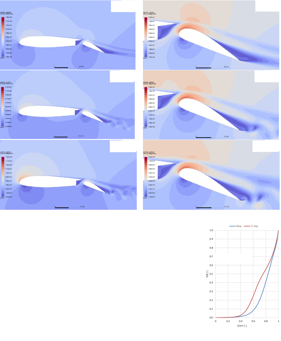
Figure 15 – Velocity contours for outboard airfoil with flaps extended and different angles of attack.
To analyse the optimisation potential, the development of the boundary
layer velocity profile was examined for different angles of attack (Figure
16). Although a degradation of the velocity profile can be observed with
increasing angle of attack, no flow reversal occurs even at larger angles
of attack such as 11°. Consequently, it is unlikely to achieve any
measurable stall speed reduction by placing VGs on the main wing of this
outboard section.
Aerodynamic Evaluation of the Inboard Airfoil (WS 35)
Investigations were performed at a Re = 4.2 ∙ 10
6
based on the clean wing
chord (1.974 m). Again, the free stream velocity was set to 113 km/h and
the flap was fully extended. The resulting polars are presented in Figure
18. In contrast to the outboard airfoil, no transient calculations were
required for the inboard airfoil. The inboard section shows only very
moderate flow separation on the flap, as shown in Figure 17. This can
2 deg
Figure 16 – Boundary
Layer Profiles (WS 226).
90% Chord
2 deg
4 deg
4 deg
11 deg
11 deg

10
OPTIMISATION OF VORTEX GENERATORS FOR STALL SPEED REDUCTION
be attributed to better inflow conditions, as the main wing is free from secondary control surfaces at this
section, further underpinning the findings outlined in the previous subchapter regarding the flap-
mounted vortex generator retrofits. Little to no flow separation occurs on the flap and the flow over the
main wing remains attached up until 13°. The confluent boundary layer on the flap and the turbulent
wake of the main wing are very prominent at 13°. These phenomena are corroborated by multiple
numerical studies performed on high lift devices supporting the validity of the CFD framework [13][14].
Figure 17 – Velocity contours for inboard airfoil with flaps extended and different angles of attack.
The velocity contour plots also show minimal optimisation potential for this airfoil section, particularly
since flap flow remains attached across the angle of attack range. This is underpinned by the boundary
layer velocity profiles which show no flow reversal hinting at flow separation onset (Figure 19).
1.5
2
2.5
3
3.5
-5 0 5 10 15 20 25
Cl
alpha [°]
Steady - well correlated
Steady - uncorrelated
1.5
2
2.5
3
3.5
0 0.2 0.4
Cl
Cd
Steady - well correlated
Steady - uncorrelated
Figure 19 – Boundary layer
profiles (WS 35) at 90 % chord.
Figure 18 - Aerodynamic polars inboard airfoil WS 35.
0 deg
0 deg
13 deg
13 deg
11
OPTIMISATION OF VORTEX GENERATORS FOR STALL SPEED REDUCTION
6.
Scope of optimisation
Performing numerical optimisation of a VG arrangement for an entire wing is an enticing idea. However,
due to phenomena such as cross flow each VG pair would have to be optimised individually creating a
design space in excess of 100 dimensions. Such an optimisation is not feasible in combination with
high fidelity CFD simulations.
A reasonable simplification to cut down the enormous computational demands would be the separate
optimisation of a VG design for a 2.5 D inboard and a 2.5 D outboard section. Here incorporation of
crossflow conditions by appropriate pressure boundaries gained from clean finite wing simulations
would be desirable. Subsequently, a linear interpolation between these two VG designs could deliver a
VG design for the entire aircraft. However, the computational demands associated with this concept
remain excessive. Trapezoidal counter-rotating vane type VGs were identified as most promising for
the intended application. Other studies have pointed to a low influence of the design parameter length
on performance and indicated a clear trend for the design parameter thickness. Choosing fixed values
for these design parameters causes a minimum of five design parameters to remain for a complete
optimisation of a VG pair, namely height, orientation, chordwise position, spacing within a pair and
spacing between VG pairs. Based on what Gano, Kim and Brown [15] found in their Kriging study for a
four-dimensional problem, a five dimensional problem would require an order of magnitude of no less
than 500 simulations to build a model of suitable quality. If several objectives at different operational
states are to be optimised, e.g. low drag at cruise and high lift at a large angle of attack, the number of
required simulations is multiplied by the number of operational states to be considered. Performing this
optimisation for 2 airfoil sections doubles the required number of simulations again. Consequently,
optimising two airfoil sections for two operational states would require at least 2000 simulations. It must
be emphasised that the stated numbers are only an educated guess. The number of required
simulations is influenced significantly by the complexity of the multidimensional relationship – which
obviously is unknown. However, although it is not possible to tell how many simulations are actually
required, the number of simulations is likely beyond the scope of an optimisation study such as this
considering the high cell size required to resolve the flow induced by vortex generators. Furthermore, it
defies logic to perform such a high number of simulations without first investigating the potential of such
an undertaking, which seems to be limited as shown by the baseline investigations.
This project is aiming for an exploration of the potential for lift increase at low speeds for the Cessna
208 by a retrofit of passive vortex generators. Consequently, the optimisation was limited to one airfoil
section and the single objective to improve lift at the original stall speed and at a high angle of attack
with fully extended flaps. However, this only reduces the number of required simulations by a factor of
four, requiring further simplification. There are three options to further cut down the computational
demands. First the mesh size could be reduced significantly which would entail losing the capability to
accurately resolve the flow reenergisation by VGs. Secondly a reduced number of simulations could be
conducted leading to a poor Kriging model quality. Thirdly the number of design parameters could be
decreased to four. While the first two options would lead to results with little physical relevance the third
option “only” involves the danger of missing the optimal solution and thus seems to be the only
acceptable simplification to be made. Although all five design parameters are highly interdependent
(refer to Figure 3) the design parameters height, orientation, spacing within a VG pair and spacing
between VG pairs are more closely coupled. They determine the range of efficacy of the created
vortices by controlling their size as well as the spacing between them. Thus, the subsequent
optimisation will be performed for a fixed chordwise position with a VG installation at 20 % chord of the
main wing as educated guess. This position combines low airfoil curvature, high kinetic energy input
and minimal degradation of the stall behaviour. From the literature review individual optimisation ranges
for the design parameters were determined that maximise the likelihood of including the optimal VG
design in the design space. The corresponding optimisation boundaries are presented in Table 2.

12
OPTIMISATION OF VORTEX GENERATORS FOR STALL SPEED REDUCTION
Table 2 - Selected Optimisation Parameters and Range.
Type (fixed)
spaced counter-rotating trapezoidal vanes
Length (fixed)
4ℎ
Thickness (fixed)
0.5
Height
0.5 − 1.8
Orientation
8° to +18°
Chordwise position (fixed)
20% chord main wing
Spacing between VG pairs
4.5ℎ − 10ℎ
Spacing within a VG pair
1ℎ − 2.5ℎ
Care had to be taken, that the design space boundaries are not mutually exclusive, e.g. the VG trailing
edges of neighbouring VG pairs must be separated enough to allow for the prism layer to be generated
around the VGs. Further, the inboard section was chosen for the optimisation. While the potential for
aerodynamic improvement was deemed to be equally low as the outboard section, the scanned inboard
section is representative of about 50 % of the wing due the arrangement of secondary control surfaces.
In contrast, the outboard section is only representative of the spoiler region which has a modified flap
bay geometry. Moreover, for the inboard section jib shape and flying shape should be almost identical,
thus the inboard section allows for the investigation of the actual flying shape. Additionally, an angle of
attack of 14 degrees was defined for the high lift optimisation as this is the largest angle that could be
validated against wind tunnel data.
7.
Vortex Generator Optimisation
To find an optimal VG design or trends for an optimal region, a Kriging model based on 60 sampling
points was built and subsequently optimised. The individual steps of the optimisation process are
described in the following sections.
In order to provide some further reassurance for the CFD-framework and modelling approach, a sample
simulation of the vortex flow was compared to experimental data obtained by Ashill et al. [15].
Figure 20 shows the surface normal velocity distribution (or up- and downwash velocity) at several
streamwise locations downstream of the vortex generators for both numerical data obtained in this study
CFD result
-1
-0.5
0
0.5
1
1.5
-3.55 0 3.55
v/U∞ [-]
z/h [-]
0.66 h
7.3 h
27.3 h
1 h
4 h
10 h
Wind tunnel result
Figure 20 - Surface normal velocity induced by VGs for CFD and wind tunnel tests [5].

13
OPTIMISATION OF VORTEX GENERATORS FOR STALL SPEED REDUCTION
and experimental data. The similarities in velocity distributions hint at suitable accuracy with regard to
the physical representation of the streamwise vortex development. Further, the vortex cores show
similar lateral movement as denoted by the intersections with the horizontal axis. Relatively lower vortex
decay of in the numerical model compared to the experimental data hints at decent vortex generator
design, especially considering that the k-omega SST turbulence model tends to under predict
streamwise vortex strength [20].
Apart from the numerical model, the quality of the Kriging
model has a decisive influence on the validity of the
optimisation result. The Kriging model was validated against a
smaller subset of data. This data was obtained using the more
computationally expensive CFD models with 2 VG pairs, which
were replaced by a more efficient approach soon after. The
validation revealed moderate agreement of the predictions
(Figure 21), however, well within limits for the analysis of
general trends. The average absolute error determined with the
cross-validation data was a deviation of ∆C
L
of 0.34%.
The Kriging model was used in conjunction with a particle
swam optimisation algorithm to predict global optima in the
design space. The optimisation algorithm was tuned to be
suitable for four dimensional problems by evaluating the Shekel
function. A swarm size of 300 particles reliably delivered
accurate results. Consequently, it was possible to prove the
reliability of the numerical setup, compromising CFD, Kriging surrogate modelling and particle swarm
optimisation.
Figure 23 visualises the four-dimensional Kriging model and thus shows the results of the entire
optimisation. For each of the nine diagrams the design parameters height and orientation are fixed while
the ordinate represents the optimisation range of the design parameter spacing within one VG pair and
the abscissa accordingly for the spacing between VG pairs. However, the constant value assumed for
height and orientation grows between the diagrams as indicated by the arrows. Finally applying the
particle swarm optimisation on the Kriging model, a maximum lift increase of 1.22 % was found for the
parameters compiled in Table 3 and Figure 22. This corroborates the assumptions about the low
potential for lift increase outlined in the previous chapters.
Table 3 - Overview of optimal direct design parameters
Design Parameter
Latin Hypercube Value
Design Space
Height
1.13
9.4 mm
Orientation
18 °
18 °
Spacing within a VG pair
2.5 h
23.5 mm
Spacing between pairs
7.62 h
71.66 mm
Interestingly only a very moderate improvement of lift
was achieved, while the potential degradation was
fourfold. The results for the VG spacing and the
spacing of VG pairs is within range of previously
conducted numerical and experimental studies,
identifying an even spacing as extremely beneficial. An
optimal VG spacing of about 2.5 h was also identified
by other studies, such as [16] (numerical) and [17]
(experimental). The optimal spacing of VG pairs of 6 h,
near the optimum found in this study, was also found
in other studies.
Figure 21 – Validation Kriging
surrogate model.
Figure 22 - Optimal vortex generator design.

14
OPTIMISATION OF VORTEX GENERATORS FOR STALL SPEED REDUCTION
Figure 22 - VG spacing and the spacing between pairs with varying height and orientation.
The in-depth analysis of the connections between the four direct design parameters shows a strong
dependency on the parameter height. Generally, with increasing height the efficacy of the vortex
generators appears to be improved. At low to moderate VG heights, the adverse effect of a large
incidence angles producing strong vortices coupled with low spacing between both VGs and VG pairs
is particularly prominent. This can be attributed to the increased mutual interference between vortices.
At lower heights interference with the wall-
shear layer is increased as well.
Three local optima can be identified of
which one is global. With increasing VG
height, a lower VG inclination seems to be
favourable which fits to the findings of Yao
et al. [18]. This may be attributable to
larger VGs stalling at lower angles of
attack, thus reducing efficacy [18]. Quite
clearly a VG spacing of 2.5 h is common
for all optima, hinting at a general trend as
corroborated by the studies outlined
before.
x
∆
[%]
Figure 23 - Vortex Formation at the VG edges.
15
OPTIMISATION OF VORTEX GENERATORS FOR STALL SPEED REDUCTION
The analysis of the flow field behind the vortex generators (Figure 23) showed two separate vortex
systems. A high energy vortex system originating from the leading edge of the vortex generator and a
larger, lower energy system encapsulating the former. While this effect was not further investigated in
this study it is assumed that while initial mixing may be increased, the excess interference within in this
vortex system may be adversely affecting vortex strength decay. As all reviewed studies only compared
different VG shapes (triangular, trapezoidal and rectangular) in terms of its impact on aerodynamic
indices, an evaluation of the created vortex systems itself may offer further scope for research.
8.
Conclusion
Eight geometric design parameters for the design of vortex generators were identified, which are: type,
height, orientation, chordwise position, length, thickness, spacing within a VG pair and spacing between
VG pairs. In order to guide vortex generator design in subsonic flow an allocation was presented how
these geometric design parameters trigger three physical flow effects: range of efficacy, kinetic energy
input and drag. Correct dimensioning of these design parameters is essential to avoid a degradation of
the aerodynamic performance which shows the need for design optimisation. Furthermore, most of the
design parameters are highly interdependent which makes a numerical optimisation the only
reasonable approach.
In order to perform a sound optimisation based on valid results, accurate baseline geometry data is
fundamental. 3D laser scanning was identified as a powerful approach to reverse-engineer the unknown
jig shape of a wing. Subsequently, the current state of the Cessna 208 wing was analysed based on
two representative cross-sections. The results suggest little potential for lift increase due to the
installation of vortex generators on the main wing. However, it was found that the region of the flap
behind the spoiler separates almost over the entire angle of attack range in contrast to the rest of the
flap. Cessna offers a VG retrofit kit for exactly that part of the wing, increasing confidence in the
numerical results. Consequently, installing this retrofit kit on the aircraft of MAF International is
suggested to achieve a first lift increase. The deviation in aerodynamic performance between the
different cross sections is caused by only a small modification of the slot geometry between the main
wing and flap, highlighting the importance of the conducted 3D laser scanning to create meaningful
results.
Subsequently, a VG optimisation for the scanned inboard section was performed at an angle of attack
of 14° at stall speed in order to further investigate the optimisation potential of placing VGs on the main
wing. However, in order to accommodate the high computational demands, set by accurate CFD
simulations and the creation of a multidimensional Kriging surrogate model, the optimisation was limited
to the design parameters height, orientation, spacing within a VG pair and spacing between VG pairs.
While the literature review delivered evidence to confidently fix three design parameters, it would have
been preferable to include the chordwise position in the optimisation procedure. The performed
numerical optimisation confirmed the assumptions made in the aerodynamic baseline analysis. There
is very limited potential for aerodynamic performance improvement of the Cessna 208 wing by installing
vortex generators on the main wing. While most VG designs lead to a degradation of the aerodynamic
performance, the optimal solution only suggested a lift improvement of 1.2%.
However, the performed optimisation gave interesting insights into the interaction of the optimised
design parameters which may help to enhance the understanding of vortex generators. Optimisation
pointed towards a design with equally spaced VGs. This way vortices are more separated reducing
rapid vortex decay due to mutual interference and thus creating a long range of efficacy. As other
studies yielded similar results a equal VG spacing might be a good design rule to follow as long as a
large range of efficacy is desired. Furthermore, the findings suggest to reduce the VG incidence angle
with increasing height.

16
OPTIMISATION OF VORTEX GENERATORS FOR STALL SPEED REDUCTION
9.
References
[1]
MAF International: https://www.maf.org/
[2]
Lin, JC Review of Research on Low-Profile Vortex Generators to Control Boundary-Layer Separation,
Progress in Aerospace Sciences 38 389–420, 2002.
[3]
Fouatih, OM, Medale, M, Imine, O & Imine, B Design Optimization of the Aerodynamic Passive Flow Control
on NACA 4415 Airfoil using Vortex Generators, European Journal of Mechanics - B/Fluids, vol. 56, pp. 82-96,
2016.
[4]
Ashill, P, Fulker, J & Hackett, K Research at DERA on Sub-Boundary Layer Vortex Generators (SBVGs), 39
th
AIAA Aerospace Sciences Meeting and Exhibit, Reno, 2001.
[5]
Ashill, P, Fulker, J & Hackett, K Studies of Flows Induced by Sub-Boundary Layer Vortex Generators
(SBVGs), 40
th
AIAA Aerospace Sciences Meeting & Exhibit, Reno, 2002.
[6]
Lin, J Control of Turbulent Boundary-Layer Separation using Micro-Vortex Generators, 30
th
AIAA Fluid
Dynamics Conference, Norfolk,1999.
[7]
Rao, D & Kariya, T Boundary-Layer Submerged Vortex Generators for Separation Control - An Exploratory
Study, 1
st
AIAA National Fluid Dynamics Conference, Cincinnati, 1988.
[8]
Gámiz, UF Fluid Dynamic Characterization of Vortex Generators and Two-Dimensional Turbulent Wakes,
PhD thesis, Universitat Politècnica de Catalunya, Barcelona, 2013.
[9]
Kerho, M, Hutcherson, S, Blackwelder, RF & Liebeck, RH Vortex Generators used to Control Laminar
Separation Bubbles, AIAA Journal of Aircraft, vol. 30, no. 3, pp. 315-319, 1993.
[10]
Thomson, K & Schulze, E Delivering Fuel and Emissions Savings for the 777, AERO Magazine, no. 35, 2009.
[11]
Micro AeroDynamics Inc. 2018b, VG Kits for Cessna, Micro AeroDynamics Inc.,
<https://microaero.com/category/vg-kits/cessna-vg-kits/>.
[12]
Micro AeroDynamics Inc. 2018a, CESSNA 207 Series MICRO Vortex Generator Kit, Micro AeroDynamics
Inc., viewed 10.08.2018.
[13]
Narsipur, S, Pomeroy, B & Selig, M CFD Analysis of Multi-Element Airfoils for Wind Turbines, 30
th
AIAA
Applied Aerodynamics Conference, New Orleans, 2013.
[14]
Ying, SX, Spaid, FW, McGinley, CB & Rumsey, CL Investigation of Confluent Boundary Layers in High-Lift
Flows, AIAA Journal of Aircraft, vol. 36, no. 3, pp. 550-562, 1999.
[15]
Gano, S, Kim, H & Brown, D Comparison of Three Surrogate Modelling Techniques: Datascape, Kriging, and
Second Order Regression,11
th
AIAA/ISSMO Multidisciplinary Analysis and Optimization Conference,
Portsmouth, 2006.
[16]
Fox, J, Bil, C & Carrese, R Particle Swarm Optimization with Surrogate Modelling of Passive Vortex
Generators, 55
th
AIAA Aerospace Sciences Meeting, Grapevine, 2017.
[17]
Godard, G & Stanislas, M Control of a Decelerating Boundary Layer. Part 1: Optimization of Passive Vortex
Generators, Aerospace Science and Technology, vol. 10, no. 3, pp. 181-191, 2006.
[18]
Yao, C, Lin, J & Allen, B Flowfield Measurement of Device-Induced Embedded Streamwise Vortex on a Flat
Plate, 1
st
AIAA Flow Control Conference, St. Louis, 2002.
[19]
Shelton, A, Abras, J, Jurenko, R & Smith, M Improving the CFD Predictions of Airfoils in Stall, 43
rd
AIAA
Aerospace Sciences Meeting and Exhibit, Reno, 2005.
[20]
Florentie, L, Van Zuijlen, A & Bijl, H Towards a Multi-Fidelity Approach for CFD Simulations of Vortex
Generator Arrays, 6
th
European Conference on Computational Fluid Dynamics, Barcelona, 2014.
[21]
Tetervin, N Tests in the NACA Two-Dimensional Low-Turbulence Tunnel of Airfoil Sections Designed to have
Small Pitching Moments and High Lift-Drag Ratios, National Advisory Committee for Aeronautics, CB 3I13,
1943.
Contact Author Email Address
Copyright Statement
The authors confirm that they, and/or their company or organization, hold copyright on all of the original material
included in this paper. The authors also confirm that they have obtained permission, from the copyright holder of
any third party material included in this paper, to publish it as part of their paper. The authors confirm that they
give permission, or have obtained permission from the copyright holder of this paper, for the publication and
distribution of this paper as part of the ICAS proceedings or as individual off-prints from the proceedings.
