
ESTATE OFFICE
SECTION 34
DOCUMENTATION
Table of Contents
34.0 DOCUMENTATION ................................................................................................................ 4
34.1 DESIGN PROCESS REQUIREMENTS .......................................................................................... 4
34.1.1 Roles and Responsibilities ............................................................................................ 4
34.1.2 Interfaces with Other Disciplines ................................................................................. 4
34.1.3 Non-Conformance Approvals ....................................................................................... 4
34.2 GENERAL REQUIREMENTS ...................................................................................................... 5
34.3 REFERENCES ........................................................................................................................... 5
34.3.1 Australian Standards:................................................................................................... 5
34.3.2 Open Standards: .......................................................................................................... 6
34.3.3 Other Industry Standards, Guidelines, and Conventions:.............................................. 6
34.3.4 Project Documents: ..................................................................................................... 6
34.3.5 System Documents: ..................................................................................................... 6
34.4 INFORMATION EXCHANGE ..................................................................................................... 6
34.4.1 General ....................................................................................................................... 6
34.4.2 Information Requests (Building Records) ..................................................................... 7
34.4.3 Site and Infrastructure Records ................................................................................... 7
34.4.4 Enlighten ..................................................................................................................... 7
34.5 SUBMISSION INSTRUCTIONS .................................................................................................. 7
34.5.1 General ....................................................................................................................... 7
34.5.2 Verification .................................................................................................................. 8
34.5.3 Method of Transmission .............................................................................................. 8
34.5.4 Letter of Transmittal .................................................................................................... 8
34.5.5 Project Drawing Register ............................................................................................. 9
34.5.6 JCU Drawing Register ................................................................................................... 9
34.6 FILE FORMATS AND NAMING CONVENTIONS ....................................................................... 10
34.6.1 General ..................................................................................................................... 10
34.6.2 Project Identification Number.................................................................................... 10
34.6.3 Discipline Code .......................................................................................................... 10
34.6.4 Drawing file name convention ................................................................................... 10
34.6.5 Document File Naming Convention ............................................................................ 10
34.6.6 BIM File Naming ........................................................................................................ 11
34.6.7 CAD File Naming ........................................................................................................ 11
JCU Design Guidelines Version 3 Page 1 of 35

ESTATE OFFICE
34.6.8
Revision Sequencing .................................................................................................. 11
34.6.9 File Formats ............................................................................................................... 11
34.6.10 Revit (RVT) File Format ............................................................................................ 12
34.6.11 Industry Foundation Classes (IFC) File Format .......................................................... 12
34.6.12 Portable Document Format (PDF) ............................................................................ 12
34.6.13 Design Web Format XPS File (DWFx) ........................................................................ 12
34.7 RECORD DOCUMENTS / AS-BUILTS ....................................................................................... 13
34.7.1 General ..................................................................................................................... 13
34.7.2 Record Model ............................................................................................................ 13
34.7.3 Building Record Deliverables ..................................................................................... 13
34.7.4 Interim BIM Model .................................................................................................... 14
34.7.5 As-Built Topographic Survey ...................................................................................... 14
34.8 EMERGENCY EVACUATION DIAGRAMS ................................................................................. 14
34.9 OPERATING AND MAINTENANCE MANUALS ......................................................................... 15
34.10 BIM STANDARDS ................................................................................................................ 15
34.10.1 General ................................................................................................................... 15
34.10.2 Methodology ........................................................................................................... 16
34.10.3 BIM Use ................................................................................................................... 16
34.10.4 Model Development Methodology .......................................................................... 17
34.10.5 Level of Development (LOD) .................................................................................... 18
34.10.6 Software .................................................................................................................. 20
34.10.7 Modeling in Revit .................................................................................................... 20
34.10.8 Model setup and project templates ......................................................................... 20
34.10.9 Model naming conventions ..................................................................................... 21
34.10.10 View naming conventions...................................................................................... 21
34.10.11 Object naming conventions ................................................................................... 21
34.10.12 Object property/parameter ................................................................................... 22
34.10.13 Sheets and Views .................................................................................................. 22
34.10.14 Model Exchange .................................................................................................... 23
34.10.15 Model Ownership .................................................................................................. 23
34.11 CAD STANDARDS ................................................................................................................ 24
34.11.1 General ................................................................................................................... 24
34.11.2 Plan Sets .................................................................................................................. 24
34.11.3 Layer Naming .......................................................................................................... 24
34.11.4 Presentation Styles .................................................................................................. 25
34.11.5 Drawing Purge ......................................................................................................... 25
34.11.6 Exported Files .......................................................................................................... 25
34.12 GEOGRAPHIC INFORMATION SYSTEM (GIS) ........................................................................ 26
34.12.1 General ................................................................................................................... 26
JCU Design Guidelines Version 3 Page 2 of 35
ESTATE OFFICE
34.12.2
Survey Drawings ...................................................................................................... 26
34.12.3 As Constructed Services Drawings ........................................................................... 26
34.12.4 Water and Chilled Water Networks ......................................................................... 27
34.12.5 Sewer and Storm Water (Gravity) Networks ............................................................ 27
34.12.6 Electricity Networks................................................................................................. 27
34.12.7 Communications Networks ...................................................................................... 28
34.12.8 Drawing Attributes Blocks........................................................................................ 28
34.12.9 Services Drawing Layers .......................................................................................... 29
34.13 APPENDIX A - DRAWING SUBMISSION CHECKLIST .............................................................. 33
34.14 APPENDIX B - SHEET NUMBERING CONVENTION ................................................................ 34
34.14.1 Discipline Designators.............................................................................................. 34
34.14.2 Sheet Types ............................................................................................................. 35
34.14.3 Sequence Numbers ................................................................................................. 35
Version Date Authors Summary of Changes
1
9 April 2013
Multitech for JCU
First Edition
2 30 September
2013
Manager, Infrastructure
Services
Revised with JCU comments
2.5 14 August 2014 WA for JCU
3 19/8/14 Issue to web
JCU Design Guidelines Version 3 Page 3 of 35

ESTATE OFFICE
34.0 DOCUMENTATION
34.1 DESIGN PROCESS REQUIREMENTS
34.1.1 Roles and Responsibilities
JCU does not wish to be separated from the design process, regardless of whether the project is
traditionally delivered, delivered through Managing Contractor, D&C contractor or other.
34.1.1.1 Traditional Delivery
Where traditional delivery is chosen, the framework may be through a Principle
Consultant (such as an Architect or Project Manager), or direct to JCU.
The Principal Consultant is to arrange workshops with the JCU Deputy Director – Planning
and Development, Manager, Infrastructure Services, Manager, Asset Strategy and
Maintenance and other technical staff as directed by these managers from initiation of
schematic design.
34.1.1.2 Managing Contractor Framework
Arrange workshops and information issues throughout the design process with the JCU
Deputy Director – Planning and Development, Manager, Infrastructure Services,
Manager, Asset Strategy and Maintenance and other technical staff as directed by these
managers (through the Managing Contractor and JCU’s Project Manager).
34.1.1.3 Communication Arrangements
All communication with JCU is to be via the JCU Project Manager. Minutes of any design
review meetings etc. are to be provided to all participants via the JCU Project Manager.
34.1.2 Interfaces with Other Disciplines
Ensure that all works necessary for the complete installation and successful operation are advised to
other consultants and specified as interface with other engineering disciplines, professions or
specialists.
Ensure that information required to accurately design the services is obtained from other
consultants as required.
34.1.3 Non-Conformance Approvals
All project team members (for example Consultants, D&C Contractors, Principal Consultants,
Internal/External project managers, subcontractors etc.) are responsible for delivering the project in
accordance with the project brief, these guidelines, user group information and other contractual
documents.
Where there are sound engineering reasons to deviate from these documents, a written non-
conformance request is to be submitted to the Deputy Director – Planning and Development via the
JCU Project Manager.
This could apply when the project involve aspects, scope, technologies, locations or other
applications that are not specifically briefed or covered by the Design Guidelines, the non-
conformance request will include clear information on:
• Technical Aspect that is not covered
• A range of options to address the issue
• Time and costs implications for each option
JCU Design Guidelines Version 3 Page 4 of 35

ESTATE OFFICE
• Effect of the aspect on the design and on other trades
• Effects on users, maintenance, access, life of plant, energy efficiency, cost
• Effects on future re-allocation of the space / system etc.
• Recommended solution to the issue
A Non-Conformance register is to be maintained by the Consultant and the details of each request
plus the outcome are to be recorded.
34.2 GENERAL REQUIREMENTS
It is important to document all changes to JCU facilities. JCU uses a variety of systems to track and
record building work and other activities. This includes infrastructure, services, operations,
maintenance, space programming, and asset and facilities management. Accurate information is
critical for effective facilities and asset management.
Building Information Models (BIM) are used to centralise the storage of information relating to
buildings. These models are managed by the Design Office.
JCU’s Geographical Information System (GIS) is the centre of information relating to site services and
infrastructure. The GIS is managed by the Design Office, JCU.
Changes to the built environment and infrastructure directly affect the day-to-day operations of the
University. The following list illustrates some of the areas that are affected by building change:
• Emergency evacuation diagrams
• Concept Safety online induction update
• Fire Wardens training
• Room Numbers
• Maintenance records
• Keys and Security
• Labels and signage
• Occupancy (Space & Timetabling)
• Chargeback (Faculty occupied areas, leased spaces)
• Fabric renewal / Maintenance schedule (Asset Management)
• Compliance with standards and codes and regulations
• GIS records
• Student Association activities and records
It is vital that all changes to the built environment are recorded and delivered to the University. To
ensure compatibility with JCU’s building and infrastructure management systems, Record
Documentation shall be delivered as specified in this section.
Note: This section is not a guideline for all project documentation deliverables. This section is
focussed specifically on Record Documentation, that is, the As-Constructed or As-Built deliverables.
34.3 REFERENCES
This section is written with reference to the following documents:
34.3.1 Australian Standards:
AS 1100.101-1992 Technical drawing - General principles
AS 1100.201-1992 Technical drawing - Mechanical engineering drawing
AS 1100.301-2008 Technical drawing - Architectural drawing
JCU Design Guidelines Version 3 Page 5 of 35

ESTATE OFFICE
AS 1100.401-1984 Technical drawing - Engineering survey and engineering survey design
drawing
AS/NZS 1100.501:2002 Technical drawing - Structural engineering drawing
34.3.2 Open Standards:
Omniclass
34.3.3 Other Industry Standards, Guidelines, and Conventions:
National Public Works Council – Table of Building Elements (Australian)
AEC (UK) BIM Protocol for Autodesk Revit – V2.0
NATSPEC National BIM Guide
AIA Document E202, Building Information Modeling Protocol Exhibit
34.3.4 Project Documents:
Letter of Transmittal
Project Drawing Register (template)
BIM Management Plan/ BIM Execution Plan
Project File
The Brief
The Contract
34.3.5 System Documents:
JCU Drawing Register
JCU Organisational BIM Management Plan
34.4 INFORMATION EXCHANGE
34.4.1 General
This section describes the process of information exchange between the University and
project
teams.
Types of information exchange:
1. requesting building and infrastructure data for
JCU property (information request)
2. submitting as built documentation to
JCU
On project completion, final documents (describing as built conditions) are submitted to the Design
Office for record keeping and integration with operational systems.
Information
Request
Project Work
(Local Copy)
Submission
(Update Central)
Record Model
JCU Design Guidelines Version 3 Page 6 of 35

ESTATE OFFICE
34.4.2 Information Requests (Building Records)
The building records at JCU are used to support planning projects, new building work, upgrades and
maintenance to existing facilities. The
project team may request access to these records.
JCU Building Records are maintained by the Design Office. Official requests for information may be
made via the
JCU Project Manager
1
.
JCU encourages the use of “self serve” systems where possible, including the following:
• Enlighten – Web-based GIS
EDocs – accessible through Enlighten
The url for Enlighten:
https://secure.jcu.edu.au/enlighten3
For access to Enlighten, contact the JCU Project Manager to initiate creation of a user account
34.4.3 Site and Infrastructure Records
JCU Site and Infrastructure Records are maintained by the Design Office. Official requests for
information may be made via the
JCU Project Manager
2
. Site and infrastructure details are
viewable through Enlighten. Refer Information Requests (Building Records)
for access to Enlighten.
34.4.4 Enlighten
Enlighten is the web-based Geographic Information System (GIS) application that enables controlled
access to JCU’s spatial data. Spatial data includes building footprints, roads, parking lots, paths,
creeks, cadastre, and other site features. The system also contains information about underground
assets such as communications, water, sewer, storm water, and electricity services.
All Estate Office staff, as well as Information Technology and Resources infrastructure staff, have
access to this rich spatial content through Enlighten. Users external to JCU can be trained and issued
with accounts to access the system.
Enlighten can be accessed at this URL:
https://secure.jcu.edu.au/enlighten3
34.5 SUBMISSION INSTRUCTIONS
34.5.1 General
All documents, drawings and model submissions shall be in accordance with this section.
The final drawing deliverables for each project is determined at the project level. A list of mandatory
requirements is set out in section 34.9.
1
Project Managers may use the following email alias to make relevant requests: BuildingRecords@jcu.edu.au
2
Project Managers may use the following email alias to make relevant requests:
GIS@jcu.edu.au
JCU Design Guidelines Version 3 Page 7 of 35

ESTATE OFFICE
All drawing submissions shall be accompanied with:
• Letter of Transmittal and;
• Project Drawing Register
34.5.2 Verification
All submitted documents shall meet the required standards and integrate successfully into all Estate
Office applications (e.g. MEX, BMS, GIS, FM: Systems, etc).
Submitted drawings shall be subject to verification of compliance to this standard. Any drawing or
model submission that does not substantially comply will be rejected and appropriate contract
action, including withholding of payment, noting on contractor past performance reports, and/or
other remedies, may be activated by
JCU.
The
Project Team shall not be relieved of responsibility when files are delivered if the files do not
meet established requirements or are defective.
Refer to Appendix A
for the Drawing Submission Checklist.
34.5.3 Method of Transmission
Files shall be issued to
JCU Building Records via the Project Manager.
Small file sets that are less than 5mb in size may be sent to this email address:
BuildingRecords@jcu.edu.au
Emails with attachments exceeding 5MBb should not be sent this way.
The handling of large file sets (those exceeding 5mb) shall be as agreed by the project team.
Acceptable methods include:
• Use of large file transfer functions over the internet
• Shared cloud storage space
• CD or DVD
• USB stick (preferred)
Electronic files and media submitted to
JCU must not contain computer viruses.
File transfers via the internet including cloud storage shall remain secure and confidential.
34.5.4 Letter of Transmittal
The Letter of Transmittal shall contain the following minimum information:
Project Number
Project Title/Description
Contract Number or Reference
Estate Office Project Manager or JCU contact name
Reason for Issue
Date of Issue
Reference to drawing register and attachments
Comments as required
JCU Design Guidelines Version 3 Page 8 of 35

ESTATE OFFICE
34.5.5 Project Drawing Register
The Project Drawing Register contains all finalised versions of models and drawings. It is not a
register for tracking revisions throughout the project, but rather a tool to capture the information
relating to each model, drawing, and sheet upon handover.
All relevant fields in the register shall be filled where possible.
The
project team shall supply a Project Drawing Register listing all finalised documents, including:
• Record Model Revit files
• Record Drawing (As-Constructed) AutoCAD files
• Record Drawing (As-Constructed) PDF files
The
Project Drawing Register shall match the JCU template and shall be supplied in Microsoft
Excel file format. Proprietary document transmittals are not acceptable.
The template is available for download at:
http://www.jcu.edu.au/estateoffice/info/constructionmaintenance/index.htm
Drawing Register Column Headers
File Name
Building Number
Floor Level
Project Number
Project Title
Site Address
Client Name
Consultant Name
Discipline
Drawing Number
Sheet Title
Content
Reason for Issue
Author
Revision Number
Date of Original Issue
Date of last issue
Original Sheet Size
Sheet Sequence Number
Comments/Notes
It is critical that the integrity of the Project Drawing Register is maintained. The information in this
table will be migrated to the JCU Drawing Register database (EDocs). The columns and headings
shall not be modified in any way.
34.5.6 JCU Drawing Register
The
JCU Drawing Register is the master record of every drawing relating to all building work for
James Cook University. This is managed by Design Office staff.
The register contains:
• Record Model Revit files
• Record Drawing (As-Constructed) AutoCAD files
JCU Design Guidelines Version 3 Page 9 of 35

ESTATE OFFICE
• Record Drawing (As-Constructed) PDF files (individual sheets, not one full set)
The register does not contain:
• Ad-hoc drawings generated from record models
• The incremental developments of drawings that are generated within project phases .
(This type of drawing shall be archived electronically within the project file)
Record submissions received shall be verified and migrated directly into the
JCU Drawing Register
by JCU. Record Documents will be linked to the database (EDocs).
34.6 FILE FORMATS AND NAMING CONVENTIONS
34.6.1 General
This section defines the mandatory file naming conventions and acceptable file formats for
electronic documents, drawings and models.
34.6.2 Project Identification Number
Each project shall be assigned a unique Project identifier by the JCU Project Manager. At the
inception of all projects the
JCU Project Identifier should be obtained to support the proper naming
of model files, content and other support files.
34.6.3 Discipline Code
The discipline prefix shall be the first four letters of the name as per the table below.
Discipline Prefix table
ARCH
Architect
STRU
Structural
CIVI
Civil
ELEC
Electrical
HYDR
Hydraulic
SURV
Survey
MECH
Mechanical
SPEC
Specification
COOR
Coordination
LAND
Landscaping
34.6.4 Drawing file name convention
Drawings shall be submitted with file names in the following format:
[DISCIPLINE]-[ PROJECT NUMBER]-[SHEET NUMBER]-REV-[REVISION NUMBER].XYZ
Example: ARCH-8000-01-REV-01.pdf
34.6.5 Document File Naming Convention
Documents including certificates, reports and other records relating to a building shall adhere to the
following file naming convention.
[DISCIPLINE]-[ PROJECT NUMBER]-[DOCUMENT NUMBER]-REV-[REVISION NUMBER].XYZ
Example: GEOT-8000-100-REV-A.pdf
Files shall be named to match equivalent native file format versions.
JCU Design Guidelines Version 3 Page 10 of 35

ESTATE OFFICE
34.6.6 BIM File Naming
The convention for model names shall be as follows:
[DISCIPLINE] – [PROJECT NUMBER] – [BUILDING NUMBER] -REV-[REVISION NUMBER].rvt
Example: ARCH-11111-D4-REV-B.rvt
34.6.7 CAD File Naming
CAD drawing files shall be named in the format below:
[DISCIPLINE]-[ PROJECT NUMBER]-[SHEET NUMBER]-REV-[REVISION NUMBER].XYZ
Example: ARCH-8000-01-REV-01.dwg
34.6.8 Revision Sequencing
Pre-tender documents shall use a numeric revision sequence, starting from 0.
Tender and post-tender documents shall use alphabetic revision sequence, starting from A.
34.6.9 File Formats
It is mandatory to adhere to the prescribed file formats. Alternative formats can only be deemed
appropriate if the format can be demonstrated to be compatible with existing JCU corporate
systems. Acceptance of an alternative format is at the discretion of the Deputy Director – Planning
and Development.
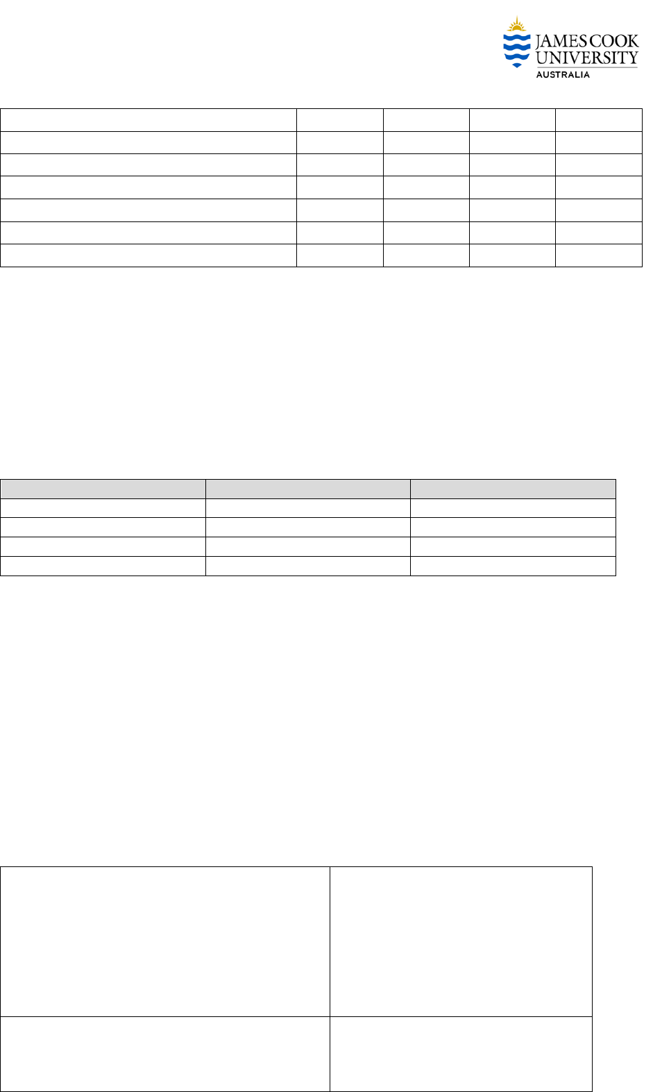
Table: Accepted File Formats
Deliverable
File format
Revit
Autocad
Word
Excel
PDF
DWFx
Project
Drawing
Register
Record
Models/As
Constructed
Architectural
Furniture, Fixtures, &
Equipment
Structural
Civil
Electrical
Lighting
Data and
Communications
Fire Services
Mechanical
Hydraulic
Finishes Schedule
Sustainability
Report
Energy
Efficiency
Report
Room Data
Sheets
JCU Design Guidelines Version 3 Page 11 of 35

ESTATE OFFICE
Operation &
Maintenance
Manual
Building Design
Report
Safe Design
Report
Design Review
3D
Site Services
34.6.10 Revit (RVT) File Format
The software version for models created and supplied in Autodesk Revit shall be nominated in the
BIM Management Plan.
Warning!
It is critical that the version of Revit specified in the BIM Management Plan is used to ensure
compatibility with all JCU’s systems. Confirm with Estate Office prior to commencement.
34.6.11 Industry Foundation Classes (IFC) File Format
Submission of model elements in IFC format is not acceptable to JCU at this time.
Refer to the following link for further information regarding Revit and IFC:
http://www.augi.com/library/myth-buster-revit-ifc
The IFC system is a data representation standard and file format used to define architectural and
construction-related CAD graphic data as 3D real-world objects. Its main purpose is to provide
architects and engineers with the ability to exchange data between CAD tools, cost estimation
systems and other construction-related applications. IFC provides a set of definitions for all object
element types encountered in the building industry and a text-based structure for storing those
definitions in a data file.
The university supports the concept of Open BIM, however the only compatible format to date that
suits current JCU systems is Autodesk Revit
file format.
34.6.12 Portable Document Format (PDF)
Documents supplied in PDF format shall conform with the PDF/A standard.
PDF/A is an ISO-standardised version of the Portable Document Format (PDF) specialised for the
digital preservation of electronic documents.
Documents shall be formatted such that sections have defined bookmarks.
34.6.13 Design Web Format XPS File (DWFx)
Acceptable file format for design review purposes.
Autodesk Design Review Software is free to download:
http://usa.autodesk.com/design-review/download/
JCU Design Guidelines Version 3 Page 12 of 35

ESTATE OFFICE
34.7 RECORD DOCUMENTS / AS-BUILTS
34.7.1 General
This section outlines the minimum requirements for Record Documents and Record Models.
For the purpose of this section, the terms building record, record drawing, as-built, and as
constructed are synonymous.
34.7.2 Record Model
Unless specified otherwise, the contract conditions shall enforce the delivery of a Record Model for
any building work carried out for the University. This applies to new buildings and renovations.
JCU requires Record Models to be Autodesk Revit Building Information Models (BIM).
The Record Model may be considered as a subset of the “As Constructed” documentation for the
explicit purpose of facilities management. The Record Model becomes the base information for the
ongoing planning, financial management, operation and maintenance of the facility.
The
project team is responsible for the creation, development and supply of a Record Model.
The level of development (LOD) of the Record Model shall be defined in the project specific
BIM
Management Plan (BMP) and form part of the Contract.
Refer to the JCU Organisational
BIM Management Plan to establish starting point for individual
projects.
34.7.3 Building Record Deliverables
The complete list of final drawing deliverables are unique to each project, and shall be defined in the
Contract. Typically, at each project milestone James Cook University requires the delivery of the
current model, electronic versions of hardcopy submissions and other files that support the intent of
the project.
Mandatory deliverables are listed in the following table.
Deliverable
Responsible
Party
Quantity
Format
Due Date
Interim BIM Model – All
disciplines as per project plan
Principal
Consultant
1 set
.rvt
3-6 months prior
to Practical
Completion
Operations & Maintenance
Manuals
Principal
Consultant All
disciplines
1 set
.pdf/paper
At Practical
Completion
Certificate of Classification
Principal
Consultant
1 set
.pdf
At Practical
Completion
Other certification documents
and dossiers (e.g. Hazardous
Areas Classification)
Principal
Consultant All
disciplines
1 set
.pdf
At Practical
Completion
As-Built Services
Principal
Consultant All
disciplines
1 set
.rvt/.dwg/.
pdf/paper
At Practical
Completion
JCU Design Guidelines Version 3 Page 13 of 35

ESTATE OFFICE
As-Built Record Model
Principal
Consultant All
disciplines
1 set
.rvt
30 days from
practical
completion
As-Built Construction Set
Principal
Consultant All
disciplines
1 set
.dwg/.pdf/
paper
30 days from
practical
completion
As-Built Topographic Survey -
Building perimeter
Principal
Consultant
Contractor
1 set
.dwg/.pdf/
paper
30 days from
practical
completion
Building Compliance Certificate
Principal
Consultant
Contractor
1 set
.pdf
30 days from
practical
completion
As-Built Site Services
Principal
Consultant All
disciplines
1 set
.dwg/.pdf/
paper
At Practical
Completion
34.7.4 Interim BIM Model
The Interim BIM Model is used by JCU to coordinate operational systems and programming for
readiness prior to practical completion of the building works.
The Interim BIM Model is a current record model (or drawing) complete with room names, room
numbers, room areas, floor finishes, and fire and emergency fixtures and equipment indicated.
These are to be submitted 3-6 months prior to practical completion.
34.7.5 As-Built Topographic Survey
A contour and detail survey 50m buffer around building perimeter recording the as-built conditions
at completion of all building and landscaping works.
Surveys shall nominate and capture a minimum of one PSM, and include two real world geographical
structure reference points with x,y,z coordinates annotated. Reference points shall be external wall
corners at diagonal opposite ends of the structure.Refer section Survey Drawings
for more details
34.8 EMERGENCY EVACUATION DIAGRAMS
Legislation mandates that all required Emergency Evacuation Signs are in place within thirty (30)
days from practical completion. The
Interim BIM Model shall be relied upon to prepare the signs.
James Cook University shall prepare all required emergency evacuation diagrams for the purpose
of supplying the wall mounted
Emergency Evacuation Signs.
JCU Design Guidelines Version 3 Page 14 of 35

ESTATE OFFICE
Minimum information required to prepare the Emergency Evacuation Signs:
• Emergency evacuation sign mounting locations
• Main path of egress
• Path of exit
• Emergency evacuation point
• Emergency exit
• Fire hose reel
• Manual call point
• Fire indicator panel
• Warden intercom
• First aid
• Switchboard
• Hydrant
• Fire extinguisher
• Gas isolation
• Zoning
Other building features relating to the fire and emergency design solution
34.9 OPERATING AND MAINTENANCE MANUALS
Details of the requirements for Operations and Maintenance Manuals are given in each section of
these Design Guidelines, generally under point XX.3.6.6.
In addition to the O&M Manuals, plant and equipment shall be modelled (BIM) to the Level of
Development as specified in the BIM Management Plan. Each item shall include attributes that
capture make, model and serial number in the model.
34.10 BIM STANDARDS
34.10.1 General
The focus of this section is to define the required level of BIM development for
JCU. This section
does not cover the implementation of BIM on projects in full detail. The adoption of the NATSPEC
National BIM Guide is preferred and, when used in conjunction with this standard, satisfies the
requirements to JCU for BIM projects.
A standard view template (Revit) named “Emergency Evacuation” shall be applied to a plan
view within the Revit model. This view template is available from the JCU BIM Template
file.
Where multiple signs are required for each floor level, the dependant view function shall
be used.
A standard title block shall be used to create the required sheet for each sign. Standard
sheets and symbols are available from the
JCU BIM Resources folder. Created sheets
shall not be deleted.
Where 2D CAD drawings are supplied in lieu of a Record Model, a clean general
arrangement plan shall be supplied by the
project team. This plan shall be free of all
annotation with the exception of room tags. A drawing is required for each level of the
building. Refer to the
CAD standards for additional presentation requirements of CAD
drawings.
JCU Design Guidelines Version 3 Page 15 of 35

ESTATE OFFICE
34.10.2 Methodology
The
project team shall refer to the NATSPEC National BIM Guide and its supporting documents to
establish the implementation of BIM on each project.
Hyperlink: http://bim.natspec.org/
A Project BIM Brief shall be prepared for each project by Estate Office. This shall form part of the
project brief.
A
BIM Management Plan (BMP), otherwise known as a BIM Execution Plan (BEP) shall be prepared
for each project by the project manager. The BMP is a formal document that defines how the
project will be executed, monitored and controlled with regards to BIM.
The
JCU Organisational BIM Management Plan shall be used for guidance when preparing the
BMP.
34.10.3 BIM Use
The nominated level of development of BIM shall support the defined uses for it. This means that
BIM data shall be prepared ‘fit for purpose’ taking into account how the BIM is intended to be used.
It is key to understand and define what BIM uses apply to the project and further for the operation
of the facility.
The current defined BIM Uses for
James Cook University include:
• Record Models
• Space Management
• Condition Data
Further practical BIM Uses are encouraged and should be well defined within the Project BIM Brief.
Typical uses include:
• Asset Management
• Maintenance Scheduling
• Record Modelling
• Space Management / Tracking
• Site Utilisation Planning
• Layout Control & Planning
• Building Systems Analysis
1
•Confirm BIM Uses
•Record in BMP
2
•Confirm Project Stages
•Select Model Development Categories (MDC) to support project stages
•Record in BMP
3
•Refer BIM requirements from Level of Development (LOD) tables
•Record in BMP
JCU Design Guidelines Version 3 Page 16 of 35

ESTATE OFFICE
• Energy Analysis
• Lighting Analysis
• Mechanical Analysis
• Sustainability Evaluation
• Disaster Planning
• Existing Conditions Modelling
• Site Analysis
• Design Authoring
• Design Reviews
• Programming
• design review in regard to spatial requirements
• Cost Estimation
• Code Validation
• Engineering Analysis
• 3D Coordination (Design)
• Structural Analysis
• Phase Planning (4D Modelling)
• 3D Coordination (Construction)
• Clash detection
34.10.4 Model Development Methodology
Models may be created and developed over a staged process that is suitable to support the required
project outcomes. This methodology shall be defined and recorded in the BMP.
The selected overall model development category may be adjusted to accommodate a specific
project or University use.
Four categories of model development are described as follows:
Model Development Category
I:
This model will support project planning through space and volume illustration, adjacencies,
and site positioning.
II:
This model will include a sufficient level of development to support document and system
review, clash detection and coordination, and support an as-built format for Owner use after
completion. If no Model Development Category (“MDC”) is identified, then MDC II will apply.
III:
This model will include all the benefits and requirements of the early model categories, and
will provide sufficient detail to support a detailed model development of systems supporting
building occupancy and facility management.
IV:
This model will include the benefits and requirements of the earlier model categories, and
support highly detailed logistical, scheduling, and estimating efforts.
JCU Design Guidelines Version 3 Page 17 of 35

ESTATE OFFICE
34.10.5 Level of Development (LOD)
The level of development for each model component is based on the model content criteria
established by AIA Document E202, Building Information Modeling Protocol Exhibit.
Hyperlink: https://aiacontracts.com/contract-documents/6524282-bim-exhibit-for-sharing-models-
with-project-participants-where-model-versions-may-not-be-enumerated-as-a-contract-document
The LOD shall match the minimum required use. Note: the minimum LOD is preferred. This shall be
outlined in the BIM Management Plan.
The content for each level of development is described as follows:
Levels of development
Authorised Uses
LOD 100 - Conceptual
Overall building massing indicative of area, height,
volume, location and orientation may be modeled in
three dimensions or represented by other data.
Analysis
Cost estimating
Schedule
LOD 200 – Approximate Geometry
Model elements are modeled as generalized systems
or assemblies with approximate quantities, size,
shape, location and orientation. Non-geometric
information may also be attached to model
elements.
Analysis
Cost estimating
Schedule
LOD 300 – Precise geometry
Model elements are modeled as specific assemblies
accurate in terms of quantity, size, shape, location
and orientation. Non-geometric information may
also be attached to model elements.
Construction
Analysis
Cost estimating
Schedule
LOD 400 – Fabrication
Model elements are modeled as specific assemblies
accurate in terms of quantity, size, shape, location
and orientation with complete fabrication, assembly
and detailing information. Non-geometric
information may also be attached to model
elements.
Construction
Analysis
Cost estimating
Schedule
LOD 500 – As built
Model elements as constructed assemblies actual
and accurate in terms of quantity, size, shape,
location and orientation. Non-geometric information
may also be attached to model elements.
General Usage
Ea
ch of the model categories has an established level of model development for each building
system. The level of development for each building system may be adjusted to reflect the
University’s requirements. This shall be outlined in the BIM Management Plan.
JCU Design Guidelines Version 3 Page 18 of 35

ESTATE OFFICE
Refer to the following example table showing levels of development for specific building systems.
The project LOD shall be defined in the BIM Management Plan.
Building System
Model Category/Level of Development
I
II
III
IV
Substructure
0
300
300
400
Structure
100
300
300
400
Enclosure*
100
300
300
400
Interior*
100
300
300
400
Conveying Systems
100
200
300
400
Plumbing
100
200
300
400
Mechanical
100
200
300
400
Fire Protection
0
100
300
400
Electrical
100
200
300
400
Equipment and Furnishings*
100
200
300
400
Special Construction
100
200
300
300
Site work
0
100
100
200
Site Improvements*
100
200
200
300
Site Utilities
100
200
300
300
* Additional LOD descriptions are provided for these building systems.
S
everal building systems are composed of elements that may require separate levels of component
development as described below:
Building System Component
Model Category / Level of Development
I
II
III
IV
Enclosure
100
300
300
400
Exterior Walls
100
300
300
400
Exterior Windows
100
200
300
400
Exterior Doors
100
300
300
400
Roof Coverings
100
200
300
400
Roof Openings
100
300
300
400
Interior
100
300
300
400
Interior Partitions
100
300
300
400
Interior Doors
100
300
300
400
Interior Specialties
0
200
300
400
Stair Construction
100
300
300
400
Wall Finishes
0
200
200
300
Ceiling Finishes
0
200
200
300
Windows
100
200
300
400
Floor/Ceiling Construction
100
300
300
400
Equipment and Furnishings
100
200
300
400
Fixed Equipment
100
200
300
400
Moveable Furnishings
100
100
200
300
Special Equipment
100
200
300
400
JCU Design Guidelines Version 3 Page 19 of 35
ESTATE OFFICE
Fixed Furnishings
100
200
300
400
Site Improvements
100
200
200
300
Roadways
100
200
200
300
Parking
100
200
200
300
Footpaths
100
200
200
300
Landscaping
0
100
100
200
Irrigation
0
100
200
200
The model categories should be reviewed together with the JCU defined requirements, adjusting the
specific levels of development for building components to support the end-user requirements. For
example: Owner may select an MDC II model for the project, but require detailed equipment data
for the mechanical system to support future expansion and systems management. The category II
model would remain as stated, with the exception of the mechanical system components which may
be set at a higher level of development.
34.10.6 Software
All software used in the development of the BIM shall be defined in the
BIM Management Plan.
Use
Product
Version
Design Authoring
Autodesk Revit
TBC
Design Review
Autodesk Design Review
TBC
Model checking
Navisworks, Solibri, other etc.
TBC
Cost Estimation
CostX, other
TBC
34.10.7 Modeling in Revit
For BIM protocols when modelling in Autodesk Revit refer to:
AEC
(UK) BIM PROTOCOL FOR AUTODESK REVIT – V2.0
Where a conflict occurs this standard shall be used.
34.10.8 Model setup and project templates
A blank Revit template consistent with this standard shall be supplied by the Design Office. This
template is a resource only, and includes the JCU shared parameters.
JCU_BIM_TEMPLATE-V0.1.
RTE
This template includes the following:
Title block
2 Standard versions (long edge and short edge) for
each paper size in the A series.
A0 – Long Edge
A0 – Short Edge
A1 – Long Edge
A1 – Short Edge
A3 – Long Edge
A3 – Short Edge
A4 – Long Edge
A4 – Short Edge
Text styles
Arial 1.8mm
Arial 2.5mm
Arial 3.5mm
Arial 5.0mm
JCU Design Guidelines Version 3 Page 20 of 35

ESTATE OFFICE
Arial 7.0mm
Room Tag
JCU Standard Room Tag
Area schedules
Shared parameter file
File name here
Common/standard family components
Refer resources.
BIM Bulletin view
Geo-referenced site plan
Townsville, Cairns, Singapore
Model naming conventions
FILE NAME CONVENTION FOR MODELS
DISCIPLINE - PROJECT NUMBER – BUILDING NUMBER – REVISION.rvt
(example: ARCH-11111-BL001-REV-A.xyz)
ARCHITECTURAL MODEL
ARCH-
CIVIL MODEL
CIVI-
MECHANICAL MODEL
MECH-
HYDRAULIC MODEL
HYDR-
ELECTRICAL MODEL
ELEC-
STRUCTURAL MODEL
STRUC-
ENERGY MODEL
ENER-
CONSTRUCTION MODEL
CONS-
COORDINATION MODEL
COOR-
34.10.9 View naming conventions
Floor levels shall be named as follows:
LEVEL
NAME
Basement
B1
Ground Floor
00
First Floor
01
Second Floor
02
Third Floor
03
Fourth Floor (and so on)
04
Mezzanine
M1
34.10.10 Object naming conventions
Objects within the Model should be named in the following format:
[Object Category]-[Type]-[Subtype]-[Manufacturer]-[Description]-[Grade/LoD]. xyz
The Type, Subtype and Manufacturer fields should be used as needed.
The following is a list of examples:
Window-Double_Hung-Andersen-400Series-Arch_Top-G3.rfa
Plumbing_Fixtures-Sink-Oval-Generic-Under_Counter-G1.rfa
Note – The condition assessment being carried out by OPUS in 2012-2013 has an elemental
breakdown based on the National Public Works Council (NPWC) tables.
JCU Design Guidelines Version 3 Page 21 of 35

ESTATE OFFICE
34.10.11 Object property/parameter
Components shall include the following basic attribute parameters regardless of the graphical
development level.
Attribute Table
Description
Manufacturer
Model
Serial Number
Asset tag number
Condition
Installation date
Expiry date
Warranty expiry date
NPWC Code
The use of hyperlinks within object attributes to Operation & Maintenance Manuals, diagram
schematics, test reports etc – broken links are not acceptable.
All objects shall be of the correct category, modeled to reflect the actual overall size and volume,
and placed in the correct relative position (location and orientation) within the model.
For created content, refer to ANZRS – Revit family creation pack – General compliance checklist C1.
http://www.anzrs.org/blog/
Also, Autodesk family style guide here:
http://usa.autodesk.com/adsk/servlet/index?siteID=123112&id=13080413
34.10.12 Sheets and Views
The central BIM shall contain the following sheets and views. Other sheets and views shall be
archived with the project files.
Table: Mandatory sheets and views in the BIM (continues next page)
View/Sheet
Content
Responsible Party
BIM Bulletin Board
Drafting view
All editors
View schedule
Schedule of all views within
the BIM
Sheet schedule
Schedule of all sheets within
the BIM
Site plan
Site boundaries
True North
Project North
Principal point of entry
Real property data
Area plans
Gross floor area
Interior Gross
Room
Estate Office
Area schedules
Gross floor area
Interior Gross
JCU Design Guidelines Version 3 Page 22 of 35

ESTATE OFFICE
View/Sheet
Content
Responsible Party
Room
Estate Office
Room schedules
Full building room schedule
Level by level filtered
schedules
Level / Room Number /
Department / Room Name /
Occupancy / Area / Floor
Finish
Window schedule
Door schedule
Plumbing and hydraulic
schedule
Electrical and data schedule
Mechanical schedule
Lighting schedule
Fire/Emergency schedule
Other equipment schedule
Floor plan
1:100 scale
Room tags, standard
North point
Building name/number/level
Major areas annotated
Emergency Evacuation plans
Refer separate standard.
Estate Office
Per level/”You are here”
Design Criteria
Drafting view
Summary of all major design
criteria
Building Classifications
Wind Classifications
Hyperlinks to certifications
Details of any specific building
compliance solutions
View Templates
Fire & Emergency floor plan
Predefined
Area floor plan
Clean floor plan
Architectural floor plan
Architectural section
Architectural elevation
34.10.13 Model Exchange
The method of model exchange between
project team members shall be defined in the BIM
Management Plan (BMP).
Considerations: Method for hosting, transfer, file security, and access of data between technical
disciplines.
34.10.14 Model Ownership
All model elements submitted become the property of
James Cook University.
JCU Design Guidelines Version 3 Page 23 of 35

ESTATE OFFICE
All content shall be free of copyright and royalty and becomes the property of
James Cook
University
34.11 CAD STANDARDS
34.11.1 General
In some instances, CAD format may be acceptable in lieu of BIM for particular projects and
deliverables. The intent of this section is to standardise the format of drawings and to ensure
compatibility with existing University systems.
34.11.2 Plan Sets
Drawing sets shall not be bound within a single file. Each drawing sheet shall be supplied as an
individual file with a corresponding file name.
34.11.3 Layer Naming
Generally, the layer naming shall be structured to enable the CAD user easy control for organising
and displaying drawing data.
JCU has adopted the method of grouping the drawing objects on layers in the syntax:
DISCIPLINE_VIEW_OBJECT
Architectural and
Structural objects
Syntax: A-WALL
All Architectural and Structural objects shall be drawn on layers with prefix
“A”, followed by the category (eg. “WALL”), with hyphen separators.
Mechanical objects
Syntax: M-DUCT
All Mechanical objects shall be drawn on layers with prefix “M”, and follow
the same syntax as Architectural layer naming
Electrical objects
Syntax: E-SWITCH
All Electrical objects shall be drawn on layers with prefix “E”, and follow the
same syntax as Architectural layer
Hydraulic objects
Syntax: H-DRAINAGE
All Hydraulic objects shall be drawn on layers with prefix “H”, and follow the
same syntax as Architectural layer
Some objects should be layered in more detail (not unlike Hatch layers) for
controlling display more easily, eg. “H-WATER-COLD”, “H-WATER-HOT”, “H-
WATER-TEPID”, etc.
Viewports
All Viewports shall be drawn on layer “Defpoints” (not just a layer which is
non-printable or switched off) unless the viewport boundary is intended to
be visible, eg. A circular viewport showing a detail
Gridlines
“A-GRIDLINES”
JCU Design Guidelines Version 3 Page 24 of 35

ESTATE OFFICE
34.11.4 Presentation Styles
Sheet Sizes
Acceptable sheet sizes as follows:
A0, A1 and A3
All sheets within a drawing set shall be of the same sheet size.
Titleblock
Shall be standard JCU titleblock available from this link.
Cross Referencing
External references (xref) files must be supplied alongside the main file.
Missing or broken links are not acceptable.
Drawing Units
Site survey plans shall be drawn in meters – Refer to the standards for GIS.
All other plans shall be drawn 1:1 in millimetres
Drawing Scales
Acceptable drawing scales to Australian Standards
Line styles and line
weights
By Layer
To Australian Standards
Gridlines
To Australian Standards
Font
To Australian Standards
Font Size
To Australian Standards
Layer Colours
To Australian Standards
Dimensions
Styles to Australian Standards
Separate layer
Model space
Annotations &
keynoting
In model space
Labelling and
tagging
Room tags to be placed in model space
Abbreviations
To Australian Standards where available
Symbols
To Australian Standards where available
Include legend in model space
Representation of
materials and
finishes
Schedules
Legends
In model space
All service lines with unique line types and colours – refer standard block.
Shape files and font
files
Must be supplied with the drawing files. Missing file warnings are not
acceptable.
Autocad file package utility is encouraged for transmission purposes.
Hatching
Do not explode hatching.
34.11.5 Drawing Purge
The “Purge all” function should be used to minimise file sizes are and remove extraneous lines,
blocks and other objects.
All content (including blocks, symbols and the like) within the drawing shall be free of
copyright and royalty conditions for the immediate and future use by the University.
34.11.6 Exported Files
Exported drawing (.DWG) files shall adhere to the above presentation styles.
JCU Design Guidelines Version 3 Page 25 of 35

ESTATE OFFICE
34.12 GEOGRAPHIC INFORMATION SYSTEM (GIS)
34.12.1 General
The university’s GIS solution is comprised of the following elements:
• Oracle Spatial Relational Database Management System
• AutoCAD Map3D and AutoCAD Civil3D
• Munsys Applications
• Munsys Management Console
• Autodesk Infrastructure Map Server
• Enlighten 3.0
Oracle spatial data is created and edited within an AutoCAD Map3D or Civil3D workspace, facilitated
by the Munsys Applications. Munsys Applications have preconfigured business rules that ensure
data quality across the whole schema.
Within the drawing workspace, objects are queried from the database and are edited using AutoCAD
and/or Munsys Applications tools. New database objects can be created from normal AutoCAD
geometry with the functionality to capture attributes during data conversion. Objects attributes
(defined in this section) should therefore be attached to the geometry as either:
1. Object Data Tables within an AutoCAD drawing
2. AutoCAD block attributes in a block associated with the geometric objects
3. As spatial object attributes within a spatial (GIS) file, including:
a. Autodesk SDF file
b. ESRI SHP file
c. Mapinfo file
The university will consider alternative file formats, should the above file formats be incompatible
with the supplier’s system.
Spatial data is styled in Autodesk Infrastructure Map Server, and access control of the data is
handled by Enlighten. Enlighten is the end-user interface for viewing, querying, analysing, and
printing spatial data.
34.12.2 Survey Drawings
Survey drawings shall be submitted in a format enabling import to the GIS, as follows:
• Drawing units shall be in metres
• Drawings shall be in Map Grid of Australia Zone 55 Projection
• Height shall be in Australian Height Datum (AHD)
34.12.3 As Constructed Services Drawings
Site plans for as-constructed services shall be in the same format as survey drawings for units,
projection, and height datum.
Services attributes such as pipe type, material, invert level etc are preferably captured as Object
Data Tables, or as geometry attributes in a spatial file. The following tables describe the attributes
to be captured.
JCU Design Guidelines Version 3 Page 26 of 35

ESTATE OFFICE
34.12.4 Water and Chilled Water Networks
The topologies for the water networks should be captured to enable network tracing. This
includes pipe locations, sizes, flow direction, and connectivity with valves and junctions
(where possible). Chilled Water and Water assets shall be captured and attributes
documented using the information structure defined in the following tables.
Points:
NODE_TYPE
NODE_ELEV
NODE_REF
WAT_CATEGORY
COMMENTS
MEX_ID
HYDRANT_SINGLE
25.115
H22
POTABLE
Note:
Please provide a logical description for NODE_TYPE.
Lines:
PIPE_DIA
PIPE_MATRL
WAT_CATEGORY
COMMENTS
100
HDPE
POTABLE
Note:
Pipe material code values are predefined. Values include:
AS Asbestos
FC Fibre Cement
PVC Polyvinyl Chloride
HDPE High Density Polyethylene
STEEL Steel
If these values are not suitable for a feature, please use a logical code.
34.12.5 Sewer and Storm Water (Gravity) Networks
Invert levels for gravity sewer and storm water pipe networks shall be captured within 0.05m
tolerance. Sewer and Storm Water assets shall be captured and documented using the information
structure defined in the following tables.
Sewer Points:
NODE_TYPE
NODE_DEPTH
NODE_COVELEV
NODE_REF
COMMENTS
SEW_CATEGORY
MANHOLE_PUB
0.95
25.225
NORMAL
Sewer Lines:
PIPE_DIA
PIPE_MATRL
START_INVELEV
END_INVELEV
COMMENTS
SEW_CATEGORY
150
PVC
22.945
22.63
NORMAL
Stormwater Points:
NODE_TYPE
NODE_DEPTH
NODE_GL
COMMENTS
WW
Stormwater Lines:
PIPE_DIA
PIPE_MATRL
START_GL
END_GL
START_IL
END_IL
COMMENTS
375
CONC
22.6
22.6
21.6
21.44
34.12.6 Electricity Networks
High Voltage and Low Voltage electricity cables are to be captured and documented using the
information structure defined in the following tables.
JCU Design Guidelines Version 3 Page 27 of 35

ESTATE OFFICE
Electricity Points:
NODE_TYPE
NODE_DESC
NODE_REF
COMMENTS
MEX_REF
CAPACITY
TRANSFORMER
WESTERN COURTS
US45
750
Electricity Lines:
CBL_SIZE
CBL_MATRL
START_TYPE
END_TYPE
COMMENTS
AG_UG
240
Al XLPE
TRANSFORMER
POLE
U9501
UG
34.12.7 Communications Networks
Communications assets shall be captured and documented using the information structure defined
in the following tables.
Communications Pits:
COMMENTS
PIT_ID
PIT_MATERIAL
12
CONC
Communications Conduits:
COMMENTS
CON_DIA
CON_MATERIAL
CON_DESC
100
PVC
1x100
34.12.8 Drawing Attributes Blocks
If supplying drawings in a spatial file format is not possible, attributes shall be captured using
AutoCAD block attributes associated with the geometry. Standard blocks for this purpose are
downloadable from the CAD/BIM Resource page. Each spatial layer should have a corresponding
attribute block to use, for example, ATT_STORMWATER_PIPE.dwg block should only be used for
stormwater pipes. In addition, attribute blocks shall be inserted on the corresponding drawing
“NOTE” layer, for example, SEWNOTE for sewer features.
The following example shows an AutoCAD drawing with associated attribute blocks for a sewer
gravity pipe. The attribute blocks are snapped to the lines’ midpoints.
Attribute blocks for point features, such as manholes, pits, and valves, shall be inserted on top of
symbol blocks. This ensures that the point features are visible in the as-constructed drawing when
the attributes layer is turned off or frozen.
JCU Design Guidelines Version 3 Page 28 of 35

ESTATE OFFICE
34.12.9 Services Drawing Layers
Layers shall be organised as:
Name
Description/Use
0
(System layer)
BLOCK
(System layer)
BUILDING
Building outlines
CMSNOTE
Cadastral notes
COMMS_CONDUITS
Communications
COMMS_PITS
CONTOURS
Topographic contours
DAM
Dams
DELETED
(System layer)
DMSLABEL_CHANNEL
Stormwater drainage
DMSLABEL_CULVERT
DMSLABEL_PIPE
EASELINE_
Easements
EASELINE_ELECTRIC
EASELINE_GENERAL
EASELINE_LEASE
EASELINE_RAILWAY
EASELINE_RESERVE
EASELINE_ROAD
EASELINE_SEWER
EASELINE_STORM
EASELINE_WATER
EASELINETXT
EASEPOLY
EASEPOLY_ELECTRIC
EASEPOLY_GENERAL
EASEPOLY_LEASE
EASEPOLY_RESERVE
EASEPOLY_ROAD
EASEPOLY_SEWER
EASEPOLY_STORM
EASEPOLY_WATER
EASEPOLYTXT
ELCABLE_
Electrical
ELCABLE_EH_OH
ELCABLE_EH_UG
ELCABLE_HV_OH
ELCABLE_HV_UG
ELCABLE_LV_OH
ELCABLE_LV_UG
ELCABLE_SL_OH
ELCABLE_SL_UG
ELDIM
ELDUCT
ELNODE
ELNODE_6.000000
JCU Design Guidelines Version 3 Page 29 of 35

ESTATE OFFICE
ELNODE_AIRLINK
ELNODE_BILLBOARD
ELNODE_DB
ELNODE_HV_JUNCTION
ELNODE_KIOSK
ELNODE_LV_JUNCTION
ELNODE_MINI_SUB
ELNODE_POLE
ELNODE_PYLON
ELNODE_SL_JUNCTION
ELNODE_STANDARD_SUB
ELNODE_STRLIGHT_POLE
ELNODE_SWITCH_STATION
ELNODE_TRANSFORMER
ELNOTE_DIM
ELNOTE_TEXT
ELSERV_SC_OH
ELSERV_SC_UG
ELZONE
FLOODLINE
Flood line
IMG_
Images
MUNICIPALITY
Cadastral
PARCEL
PARCEL_C
PARCEL_P
PATH_AREAS
Path areas
PSM
Permanent Survey Marks
RD_PARKING
Roads
RDAREA
RDCL
RDEDGE
RDINT
RDNOTE_NOTE_TYPE_TEXT
RDWALK
RIVERLINE
Riverlines and polygons
RIVERPOLY
SEWBASIN
Sanitary and trade waste
SEWDIM
SEWDIMNOTE
SEWGLABEL
SEWGPIPE
SEWNODE
SEWNOTE
SEWRESPIPE
SEWRLABEL
SEWRPIPE
SEWSERV
SEWSYM
SEWVLABEL
SEWVPIPE
JCU Design Guidelines Version 3 Page 30 of 35

ESTATE OFFICE
SPORTSFIELDS
Sportsfields
SUBURB
Cadastral
SURVEY_MARKS
Topographic survey marks
SWCATCH
Stormwater
SWCHANNEL
SWCULVERT
SWDIM
SWNODE
SWNOTE
SWNOTE_NOTE_TYPE_DIM
SWNOTE_NOTE_TYPE_TEXT
SWPIPE
TOWN_C
Cadastral
TP_LANDUSE_JCUACAD
Town planning, zoning, cadastral
TP_LANDUSE_JCUCOLLEGE
TP_LANDUSE_JCUDISCCENT
TP_LANDUSE_JCUDVRES
TP_LANDUSE_JCUDVSTG1
TP_LANDUSE_JCUENTPARK
TP_LANDUSE_JCUNATURE
TP_LANDUSE_JCUPADDOCK
TP_LANDUSE_JCUROAD
TP_LANDUSE_JCUSCHOOL
TP_LANDUSE_JCUSPORT
TP_LANDUSE_JCUUVRES
TP_ZONING_AGRIC
TP_ZONING_AMUSEMENT
TP_ZONING_BUS_1
TP_ZONING_BUS_2
TP_ZONING_BUS_3
TP_ZONING_BUS_4
TP_ZONING_CEMETERY
TP_ZONING_COMMERCIAL
TP_ZONING_EDUCATIONAL
TP_ZONING_EXIST_PUBLIC_ROAD
TP_ZONING_GOVERNMENT
TP_ZONING_IND_2
TP_ZONING_IND_3
TP_ZONING_INSTITUTIONAL
TP_ZONING_MUNICIPAL
TP_ZONING_PARKING
TP_ZONING_PRIVATE_OPEN_SPACE
TP_ZONING_PRIVATE_ROAD
TP_ZONING_PROP_NEW_ROAD
TP_ZONING_PUBLIC_GARAGE
TP_ZONING_PUBLIC_OPEN_SPACE
TP_ZONING_RES_1
TP_ZONING_RES_2
TP_ZONING_RES_3
TP_ZONING_RES_4
JCU Design Guidelines Version 3 Page 31 of 35

ESTATE OFFICE
TP_ZONING_SAR
TP_ZONING_SPECIAL
TP_ZONING_UNKNOWN
TREES
Trees
WARD
Cadastral
WATDIM_POTABLE
Water
WATDIMNOTE_POTABLE
WATLABEL_ABANDON
WATLABEL_POTABLE
WATLABEL_RAW
WATNODE_
WATNODE_ABANDON
WATNODE_POTABLE
WATNODE_RAW
WATNOTE_POTABLE
WATPIPE_
WATPIPE_ABANDON
WATPIPE_CHILLWR
WATPIPE_CHILLWS
WATPIPE_POTABLE
WATPIPE_RAW
WATRESPIPE
WATSERV_
WATSERV_CHILLWR
WATSERV_CHILLWS
WATSERV_POTABLE
WATSERV_RAW
WATSYM_POTABLE
WATZONE_POTABLE
JCU Design Guidelines Version 3 Page 32 of 35

ESTATE OFFICE
34.13 APPENDIX A - DRAWING SUBMISSION CHECKLIST
Item Date Received
Verified against
this section
Check project identification number
Check file naming convention
Check revision sequencing
Check file formats
Letter of transmittal
Project document register (excel)
Interim Record Model (BIM)
Operations & Maintenance Manuals
Certificate of Classification
As-Built Services (.dwg)
As-Built Record Model – Architectural
As-Built Record Model – Structural
As-Built Record Model – Mechanical
As-Built Record Model – Electrical
As-Built Record Model – Hydraulic
As-Built Record Model – Topographic (Survey)
As-Built Construction Drawings (.dwg)
JCU Design Guidelines Version 3 Page 33 of 35

ESTATE OFFICE
34.14 APPENDIX B - SHEET NUMBERING CONVENTION
Drawing sheets may be numbered using the following conventions:
[Discipline Designator][Type Designator][Sequence Number]-[Sheet Title]
Example:A101-Site Plan
34.14.1 Discipline Designators
The following table indicates the primary (single) letter designations that may be used.
Designator
Name
Additional Description
Cover Sheet
G
General
Sheet list, symbols, code summary, etc.
H
Hazardous Materials
Abatement, handling, etc.
V
Survey / Mapping
B
Geotechnical
C
Civil
L
Landscape
S
Structural
A
Architectural
I
Interiors
Q
Equipment
F
Fire Protection
P
Plumbing
D
Process
M
Mechanical
E
Electrical
T
Telecommunications
R
Resource
Existing conditions / buildings
X
Other Disciplines
Z
Contractor / Shop Drawings
O
Operations
FM
JCU Design Guidelines Version 3 Page 34 of 35

ESTATE OFFICE
34.14.2 Sheet Types
The Sheet Types designator takes the drawings of a single discipline and organises them.
Designator
Name
0
General: Symbol legend, abbreviations, general notes
1
Plans
2
Elevations
3
Sections
4
Large Scale Drawings: plans, elevations, sections -- NOT details
5
Details
6
Schedules and Diagrams
7
User Defined
8
User Defined
9
3D drawings: isometric, perspective, photos
10
Space Data
34.14.3 Sequence Numbers
The final component of the sheet number is the two-digit sequence number, which is between 01
and 99. The sequence numbers do not have to be sequential so that space may be left within the set
for future additions.
JCU Design Guidelines Version 3 Page 35 of 35
