
SES Reference
Ultrastar® Data60 3000 Series
Regulatory Model H4060-J
Firmware 2000-098 (SEP)
Document D018-000936-000
Revision 01
June 2024

SES Reference Table of Contents
Table of Contents
Revision History............................................................................................................................................................................................... v
Notices................................................................................................................................................................................................................... vi
Points of Contact......................................................................................................................................................................................... vii
Chapter 1. Autonomous Behavior..................................................................................... 1
SCSI Enclosure Processor.................................................................................................................................................................... 2
Offline State......................................................................................................................................................................................................2
SAS Fabric Management.......................................................................................................................................................................2
Drive Spin-up Staggering...................................................................................................................................................................... 2
Event Logging.................................................................................................................................................................................................3
Host, Drive, and Interconnect Port Management................................................................................................................3
Thermal Management.............................................................................................................................................................................. 3
Closed Loop Fan Algorithm...................................................................................................................................................... 3
Thermal Compromise Handling..............................................................................................................................................3
Thermal Offline State.....................................................................................................................................................................4
Enclosure Shutdown....................................................................................................................................................................... 4
Chapter 2. Platform Firmware Overview........................................................................ 5
SAS Topology................................................................................................................................................................................................. 6
SG3 Utilities...................................................................................................................................................................................................... 7
LEDs....................................................................................................................................................................................................................... 8
Chassis LEDs....................................................................................................................................................................................... 8
HEM LEDs............................................................................................................................................................................................ 10
IOM LEDs...............................................................................................................................................................................................12
IOM Fan LED......................................................................................................................................................................................13
PSU LED................................................................................................................................................................................................ 14
System Fan LED..............................................................................................................................................................................15
Drive Assembly LED..................................................................................................................................................................... 16
i

SES Reference Table of Contents
Chapter 3. SMP Commands.............................................................................................17
SMP Commands Overview.................................................................................................................................................................18
Report General............................................................................................................................................................................................. 19
Report Manufacturer Information.................................................................................................................................................. 19
PHY Control....................................................................................................................................................................................................19
Zoning Support............................................................................................................................................................................................19
Chapter 4. SES Diagnostic Pages................................................................................. 20
SES Model.......................................................................................................................................................................................................21
Sequencing of SCSI Operations..........................................................................................................................................21
Reserved Bit Checking................................................................................................................................................................21
Partial SCSI Enclosure Services Pages........................................................................................................................ 22
Predictive Failure.............................................................................................................................................................................22
SES Supported Diagnostics Page (00h)................................................................................................................................22
Configuration Page (01h).....................................................................................................................................................................23
Enclosure and Threshold Diagnostic Pages (02h and 05h)................................................................................... 26
Overview of Control/Status Element Handling....................................................................................................... 26
Overview of Visual Indicator Handling........................................................................................................................... 27
Interaction of Visual Indicators and Host Initiated Identify/Fault Requests.......................................28
Page Layout....................................................................................................................................................................................... 28
Default Thresholds........................................................................................................................................................................ 32
Offsets for the Enclosure Status/Control and Threshold Out/In Pages..............................................32
Help Text Diagnostic Page (03h)................................................................................................................................................. 39
String Out/In Diagnostic Page (04h)........................................................................................................................................40
Element Descriptor Page (07h)..................................................................................................................................................... 43
Element Descriptor........................................................................................................................................................................43
Overall Element Descriptor Format.............................................................................................................................................49
Overall Element Descriptor.....................................................................................................................................................49
Additional Element Status Diagnostic Page (0Ah).........................................................................................................50
ii

SES Reference Table of Contents
Download Microcode Control/Status Diagnostic Page (0Eh)................................................................................53
Subenclosure Nickname Control/Status Diagnostic Page (0Fh).........................................................................55
Tag Data Out/In Diagnostic Page (10h).................................................................................................................................. 57
MiniSAS HD Cable VPD Diagnostic Page (17h)................................................................................................................58
Chapter 5. SES Elements.................................................................................................60
SES Element Status Codes...............................................................................................................................................................61
Array Slot.........................................................................................................................................................................................................62
Array Device Slot Element Control and Status Elements...............................................................................64
Array Slot Element Descriptor..............................................................................................................................................65
Additional Element Status Descriptor............................................................................................................................66
Enclosure......................................................................................................................................................................................................... 67
Enclosure Element Control and Status.........................................................................................................................67
Enclosure Element Descriptor..............................................................................................................................................68
Power Supply............................................................................................................................................................................................... 68
Power Supply Element Control and Status...............................................................................................................69
Power Supply Element Descriptor....................................................................................................................................70
Cooling...............................................................................................................................................................................................................70
Rear Fan Cooling Element Control and Status........................................................................................................71
Cooling Element Descriptor....................................................................................................................................................72
Temperature...................................................................................................................................................................................................72
Temperature Sensor Element Control and Status................................................................................................ 73
Temperature Element Descriptor........................................................................................................................................74
Door......................................................................................................................................................................................................................74
Door Element Control and Status.....................................................................................................................................74
Door Element Descriptor.......................................................................................................................................................... 75
ESCE................................................................................................................................................................................................................... 75
Enclosure Services Controller Electronics Element Control and Status...............................................76
Additional Element Status Descriptor—ESCE..........................................................................................................77
SAS Expander..............................................................................................................................................................................................77
iii

SES Reference Table of Contents
SAS Expander Element Control and Status............................................................................................................. 78
SAS Expander Element Descriptor.................................................................................................................................. 79
Additional Element Status Descriptor—SAS Expander.....................................................................................79
SAS Connector...........................................................................................................................................................................................80
SAS Connector Element Control and Status...........................................................................................................80
SAS Connector Element Descriptor..................................................................................................................................81
Voltage Sensor............................................................................................................................................................................................. 81
Voltage Sensor Element Control and Status.............................................................................................................81
Voltage Sensor Element Descriptor.................................................................................................................................82
Current Sensor............................................................................................................................................................................................83
Current Sensor Element Control and Status............................................................................................................83
Current Sensor Element Descriptor.................................................................................................................................84
Chapter 6. SCSI Commands........................................................................................... 85
SEP SCSI Behavior Overview......................................................................................................................................................... 86
Test Unit Ready......................................................................................................................................................................................... 86
Request Sense............................................................................................................................................................................................87
Inquiry.................................................................................................................................................................................................................87
Standard INQUIRY Data........................................................................................................................................................... 88
Supported INQUIRY Vital Product Pages................................................................................................................... 89
Send Diagnostic..............................................................................................................................................................................93
Receive Diagnostic Results....................................................................................................................................................94
Report Logical Unit Numbers...............................................................................................................................................94
Mode Select (10).............................................................................................................................................................................95
Mode Sense (10).............................................................................................................................................................................96
Log Select............................................................................................................................................................................................96
Log Sense............................................................................................................................................................................................97
iv

SES Reference Revision History
Revision History
Table 1: Revision History
Date Revision Notes
June 2024 01 Initial release
v

SES Reference Notices
Notices
Western Digital Technologies, Inc. or its affiliates' (collectively “Western Digital”) general policy does not
recommend the use of its products in life support applications wherein a failure or malfunction of the product
may directly threaten life or injury. Per Western Digital Terms and Conditions of Sale, the user of Western
Digital products in life support applications assumes all risk of such use and indemnifies Western Digital
against all damages.
This document is for information use only and is subject to change without prior notice. Western Digital
assumes no responsibility for any errors that may appear in this document, nor for incidental or consequential
damages resulting from the furnishing, performance or use of this material.
Absent a written agreement signed by Western Digital or its authorized representative to the contrary,
Western Digital explicitly disclaims any express and implied warranties and indemnities of any kind that may,
or could, be associated with this document and related material, and any user of this document or related
material agrees to such disclaimer as a precondition to receipt and usage hereof.
Each user of this document or any product referred to herein expressly waives all guaranties and warranties
of any kind associated with this document any related materials or such product, whether expressed or
implied, including without limitation, any implied warranty of merchantability or fitness for a particular purpose
or non-infringement. Each user of this document or any product referred to herein also expressly agrees
Western Digital shall not be liable for any incidental, punitive, indirect, special, or consequential damages,
including without limitation physical injury or death, property damage, lost data, loss of profits or costs of
procurement of substitute goods, technology, or services, arising out of or related to this document, any
related materials or any product referred to herein, regardless of whether such damages are based on tort,
warranty, contract, or any other legal theory, even if advised of the possibility of such damages.
This document and its contents, including diagrams, schematics, methodology, work product, and intellectual
property rights described in, associated with, or implied by this document, are the sole and exclusive
property of Western Digital. No intellectual property license, express or implied, is granted by Western Digital
associated with the document recipient's receipt, access and/or use of this document or the products
referred to herein; Western Digital retains all rights hereto.
Western Digital, the Western Digital design, the Western Digital logo, and Ultrastar are registered trademarks
or trademarks of Western Digital Corporation or its affiliates in the US and/or other countries. All other marks
are the property of their respective owners.
Product specifications subject to change without notice. Pictures shown may vary from actual products. Not
all products are available in all regions of the world.
Western Digital
5601 Great Oaks Parkway
San Jose, CA 95119
© 2024 Western Digital Corporation or its affiliates. All Rights Reserved.
vi

SES Reference Points of Contact
Points of Contact
For further assistance with a Western Digital product, contact Western Digital Datacenter Platforms technical
support. Please be prepared to provide the following information, as applicable: part number (P/N), serial
number (S/N), product name and/or model number, software version, and a brief description of the issue.
Website:
https://portal.wdc.com/s/
Email:
enterprisesupport@wdc.com
UK Import Representation Contact
PO Box 471
Leatherhead KT22 2LU
UK
Telephone: +44 1372 366000
EU Import Representation Contact
BP 80006
92135 Issy les Moulineaux, France
vii

1
Autonomous Behavior
In This Chapter:
- SCSI Enclosure Processor............................................................................................2
- Offline State....................................................................................................................... 2
- SAS Fabric Management.............................................................................................. 2
- Drive Spin-up Staggering............................................................................................. 2
- Event Logging................................................................................................................... 3
- Host, Drive, and Interconnect Port Management................................................3
- Thermal Management.................................................................................................... 3

SES Reference
1. Autonomous Behavior
1.1 SCSI Enclosure Processor
1.1
SCSI Enclosure Processor
All expanders inclduded in each IOM/HEM pair operate as a single entity known as the SCSI Enclosure
Processor (SEP). The SEP is the virtual device that implements all SES functionality defined by this
document, including:
• Enclosure management policy
• Status gathering
• Parsing and building SES pages
• Communicating with enclosure management components (LEDs, fans, power supplies, sensors, etc.)
• Staggering drive spin-up
• Enabling/disabling attached PHYs
• Handling zoning requests
1.2
Offline State
The enclosure has the ability to enter offline state. The offline state is designed to protect the enclosure and
its data, along with the larger data center ecosystem, against cases of serious risk of data or SAS fabric
corruption if the enclosure were to attempt to operate.
During offline state, the drives are powered off and are not presented to hosts. This leaves the SEP as the
only SAS target in the enclosure. In the offline state, the SEP fully responds to host commands other than
those that would cause the disk drives to be powered on or presented to hosts. The offline state is volatile,
and will not automatically recur after an enclosure reset or power cycle unless, the conditions which warrant
it, reoccur.
There are several conditions which can cause a SEP to enter offline state, including:
• Enclosure VPD data unreadable or corrupted
• Enclosure is in thermal compromise state – see Thermal Offline State (page 4)
• SEP cannot communicate with all expanders in the design
The exact reason for the particular state is reported in the Help Text Diagnostic Page (03h) (page 39) and
String Out/In Diagnostic Page (04h) (page 40).
1.3
SAS Fabric Management
The SEP autonomously performs the following functions relative to SAS fabric management:
• Configures SAS PHYs to appropriate transceiver settings
• Programs each expander with a unique SAS address from Enclosure VPD data
• Provides appropriate branding-specific Inquiry data from Enclosure VPD data
• Provides SMP initiator and target services on all expanders
• Exposes a virtual SSP initiator and target services on the primary expander only
• Enables physical layers connected to drives and host cables only if a drive/cable is connected
1.4
Drive Spin-up Staggering
When the enclosure is powered-on, all drives are automatically spun-up per the following algorithm, to avoid
drawing an excessive amount of current:
2

SES Reference
1. Autonomous Behavior
1.5 Event Logging
1. 0.5-second initial delay
2. 2 drives spun up every second until all have spun up
1.5
Event Logging
The SEP has a non-volatile event logging subsystem contained in expander-level VPD EEPROM. Entries
are time-stamped with an incrementing tick counter, or time of day in the server environment, where RTC is
available.
Entries are logged to indicate a variety of events, including:
• SEP boot events
• Entry or exit from offline state
• CRU configuration changes
• Code updates
• Crash records
Note: The event log buffer erases the oldest entries when it is full.
1.6
Host, Drive, and Interconnect Port Management
The SCSI Enclosure Processor (SEP) monitors the PHYs which connect the Serial Attached SCSI (SAS)
expanders to other devices. The monitoring indicates link up, link down, and link partial up status. A partial
link up status condition means that not all of the PHYs in a wide port have achieved linked status or not all of
the PHYs in a wide port are linked at the same link rate.
Host port interconnect link status issues are signaled using the host port light-emitting diodes (LED), and
by marking the corresponding SCSI Enclosure Services (SES) SAS Connector Element instance with Non-
Critical or Critical status.
Drive interconnect link status issues are signaled using the drive LEDs, and by marking the corresponding
SES Array Device Slot Element instance with Non-Critical or Critical status.
Expander interconnect link status issues are signaled using the chassis and HEM LEDs, and by marking the
corresponding SES SAS Expander Element instance with Non-Critical or Critical status.
1.7
Thermal Management
1.7.1
Closed Loop Fan Algorithm
The SCSI Enclosure Processor (SEP) periodically polls the current readings of both enclosure and drive
temperature sensors. It automatically adjusts the fan pulse-width modulation (PWM) values to the minimum
necessary air flow that maintains all enclosure component temperatures, including drives, at or below a
factory-set level across the ambient temperature range allowed for the product. The algorithm incorporates
both time- and temperature-based hysteresis to avoid over-compensation phenomena.
3

SES Reference
1. Autonomous Behavior
1.7 Thermal Management
1.7.2
Thermal Compromise Handling
In the event that the enclosure becomes thermally compromised, the fans will run at full speed regardless
of temperature readings. An example of an enclosure becoming thermally compromised is missing a
required customer replaceable unit (CRU), or another serious fault.
1.7.3
Thermal Offline State
If the enclosure temperature readings exceed critical values for a period of time that constitutes a risk to
continued safe operation, the enclosure enters an offline state. In an offline state, one or more drives are
taken offline. This might mean that they are spun down and powered off. The host may continue to send
and receive SCSI Enclosure Services (SES) diagnostic pages in offline state, however the SCSI Enclosure
Processor (SEP) rejects SCSI Enclosure Services (SES) requests to power up drives that have been taken
offline.
Note: The thermal shutdown condition self-resolves once temperatures have reached a safe
level.
1.7.4
Enclosure Shutdown
Certain classes of thermal fault conditions require the enclosure to autonomously shut down as much of
the enclosure as possible. If this occurs, the enclosure will return to low-power state. The host may continue
to send and receive SCSI Enclosure Services (SES) diagnostic pages in low-power state, but this condition
does not self-resolve. The intent is that user intervention follows to ascertain and mitigate the reason for the
shutdown.
4

5
Platform Firmware
Overview
In This Chapter:
- SAS Topology.................................................................................................................... 6
- SG3 Utilities........................................................................................................................7
- LEDs...................................................................................................................................... 8

SES Reference
2. Platform Firmware Overview
2.1 SAS Topology
2.1
SAS Topology
The SAS Topology of the Data60 3000 Series is shown in the following Figure 1: SAS Topology (page 6)
figure. The architecture provides six (6) x4 MiniSAS HD port host connections to the HEM. These ports can
be used with standard cables to connect to the MiniSAS HD port located on an arbitrary third party SAS
host. The availability of six (6) MiniSAS HD ports on the HEM permits daisy-chained topologies.
Figure 1: SAS Topology
6

SES Reference
2. Platform Firmware Overview
2.2 SG3 Utilities
Figure 2: Phy to Slot Mapping
2.2
SG3 Utilities
The sg3_utils package contains utilities that send SCSI commands to devices. Sg3_utils are available for
Linux and Windows platforms and can be obtained from http://sg.danny.cz/sg/sg3_utils.html. The SG3
Element Index values—provided in the tables throughout the remainder of this document—can be used with
the sg_ses command to obtain data for the specific element instance. For example, sg_ses /dev/sg2 --
page=2 --index=0,3 retrieves information for drive 4, and so on.
It is recommended that the Data60 3000 Series be used with V1.47 or later of the SG3 distribution, as this
release fixes several known issues in previous releases.
7

SES Reference
2. Platform Firmware Overview
2.3 LEDs
2.3
LEDs
This section provides information about the placement and behavior of all light emitting diodes (LEDs) on
the Data60 3000 Series platform and its components.
2.3.1
Chassis LEDs
Chassis Front LEDs
The Data60 3000 Series has three (3) LEDs on the front exterior of the chassis that display various system
statuses.
Figure 3: Chassis Front LEDs Location
Table 2: Chassis Front LEDs Behavior
Number LED Name Color Behavior
1 Identify Blue
Off – Enclosure identification is not activated
Blink @ 1 Hz (50% duty cycle) – Enclosure identification has
been activated.
2 Fault Amber
Off – Enclosure has no fault
Blink @ 1 Hz (50% duty cycle) – Enclosure has a fault
3 Power Green
Off – Enclosure is powered off
Solid – Enclosure is powered on
8

SES Reference
2. Platform Firmware Overview
2.3 LEDs
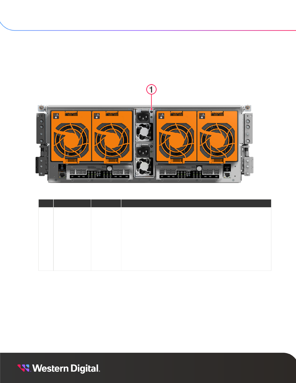
Chassis Rear LEDs
The rear of the chassis provides two (2) LEDs for each out-of-band management port (4 total) and one (1)
identify LED.
Figure 4: Chassis Rear LEDs Location
Table 3: Chassis Rear LEDs Behavior
Number LED Name Color Behavior
1
Management
Port Identify
Blue
Off – Identification of chassis or any component is not
activated
Blink @ 1 Hz (50% duty cycle) – Identification of chassis or any
component is activated
2
Management
Port Speed
Green/
Amber
Off – Management port operating at 10 Mbps
Green, Solid – Management port operating at 100 Mbps
Amber, Solid – Management port operating at 1Gbps
3
Management
Port Link/
Activity
Green
Off – No Connection
Blink – Connected, Activity
Solid – Connected, No Activity
9

SES Reference
2. Platform Firmware Overview
2.3 LEDs
2.3.2
HEM LEDs
Each host expander module (HEM) provides nine LEDs to indicate a variety of statuses (eighteen LEDs
total).
Figure 5: HEM LEDs Location
Table 4: HEM LEDs Behavior
Number LED Name Color Behavior
1
Ports 1-3
SAS Link &
Fault Status
Green/
Amber
Off – SAS cable not connected
Green, Solid – SAS cable connected
Amber, Blinking @ 1 Hz (50% duty cycle) – SAS connection
fault
2
HEM
Identification
Blue
Off – Identification of HEM is not activated
Blink @ 1 Hz (50% duty cycle) – Identification of HEM is
activated
3 HEM Fault Amber
Off – HEM has no fault
Blink @ 1 Hz (50% duty cycle) – HEM has a fault
4 HEM Power Green
Off – HEM is powered off
Solid – HEM is powered On
10

SES Reference
2. Platform Firmware Overview
2.3 LEDs
Number LED Name Color Behavior
5
Ports 4-6
SAS Link &
Fault Status
Green/
Amber
Off – SAS cable not connected
Green, Solid – SAS cable connected
Amber, Blinking @ 1 Hz (50% duty cycle) – SAS connection
fault
Note: In the event of misconfigured IOM hardware, all three HEM LEDs (Identification, Fault,
and Power) will blink at 2Hz (50% duty cycle).
11

SES Reference
2. Platform Firmware Overview
2.3 LEDs
2.3.3
IOM LEDs
Each input/output module (IOM) has three LEDs to indicate power, fault, and identification.
Figure 6: IOM LEDs Location
Table 5: IOM LEDs Identification
Number LED Name Color Behavior
1 Identification Blue
Off – IOM is not being identified
Blink @ 0.5 Hz (75% duty cycle) – IOM identification is
activated
2 Fault Amber
Off – IOM is functioning normally
Blink @ 0.5 Hz (75% duty cycle) – IOM has a fault
3 Power Green
Off – IOM is off
Solid – IOM is on
Note: In the event of misconfigured IOM hardware, all three IOM LEDs (Identification, Fault,
and Power) will blink at 2Hz (50% duty cycle).
12

SES Reference
2. Platform Firmware Overview
2.3 LEDs
2.3.4
IOM Fan LED
The IOM Fan has a single, multi-function LED to indicate a variety of statuses. See the following table for a
detailed description of the colors and associated behaviors.
Figure 7: IOM Fan LED Location
Table 6: IOM Fan LED Behavior
Number LED Name Color Behavior
1 IOM Fan LED Amber
Off – IOM Fan is on and reporting no faults
Blink @ 1 Hz (50% duty cycle) – IOM Fan is reporting faults
Blink @ 2 Hz (50% duty cycle) – IOM Fan identification is
activated
13
SES Reference
2. Platform Firmware Overview
2.3 LEDs
2.3.5
PSU LED
Each power supply unit (PSU) has a single, multi-function LED to indicate a variety of statuses. See the
following table for a detailed description of the colors and associated behaviors.
Figure 8: PSU LED Location
Table 7: PSU LED Behavior
# LED Name Color Behavior
1
PSU Multi-
Function LED
Green/
Amber
Off – PSU disconnected from power
Green, Blink @ 1Hz (50% duty cycle) – AC present and 12VSB
on
Green, Blink @ 2Hz (50% duty cycle) – PSU in firmware update
mode
Green, Solid – PSU on and reporting no faults
Amber, Blink @ 1Hz (50% duty cycle) – PSU reporting warnings
Amber, Solid – PSU disconnected from power while second
PSU is connected to power, or critical fault causing a
shutdown failure, or compatibility fault
14

SES Reference
2. Platform Firmware Overview
2.3 LEDs
2.3.6
System Fan LED
Each System Fan has a single, multi-function LED to indicate a variety of statuses. See the following table
for a detailed description of the colors and associated behaviors.
Figure 9: System Fan LED Location
Table 8: System Fan LED Behavior
Number LED Name Color Behavior
1
System
Fan LED
Amber
Off – System Fan is on and reporting no faults
Blink @ 1 Hz (50% duty cycle) – System Fan is reporting faults
Blink @ 2 Hz (50% duty cycle) – System Fan is being identified
15

SES Reference
2. Platform Firmware Overview
2.3 LEDs
2.3.7
Drive Assembly LED
The drive slot for each HDD Assembly has a single, multi-function LED to indicate a variety of statuses. See
the following table for a detailed description of the behaviors and associated meaning.
Figure 10: Drive Slot LED Location
Table 9: Drive Slot LED Identification
Number LED Name Color Behavior
1 Drive Slot LED Amber
Off – Drive has no faults
Blink @ 1 Hz (50% duty cycle) – Drive fault
Blink @ 2 Hz (50% duty cycle) – Drive identify
Note: During service events—when a drive is hot plugged or replaced and the drive installed
properly—the LED state of that drive slot will change to solid ON. This is to provide the user
with visual feedback that the drive has been successfully connected and has been discovered
by the expander. Once the enclosure has been slid back into the rack, and the OPEN bit on
the door sensor element changes from 1 to 0, the LED will return to the previously set state
(Ident, Fault, or Off).
16

17
SMP Commands
In This Chapter:
- SMP Commands Overview......................................................................................... 18
- Report General................................................................................................................ 19
- Report Manufacturer Information............................................................................19
- PHY Control......................................................................................................................19
- Zoning Support............................................................................................................... 19

SES Reference
3. SMP Commands
3.1 SMP Commands Overview
3.1
SMP Commands Overview
The following table lists the Serial Management Protocol (SMP) commands supported by Data60 3000
Series.
Note: If a section reference is provided in the Section column, the referenced section provides
additional details about the Data60 3000 Series implementation of the SMP command that is
not fully explained in the SPL-2 standard.
Table 10: SEP Supported SMP Commands
Command Name Op Code Section
REPORT GENERAL 00h Report General (page 19)
REPORT MANUFACTURER INFO 01h
SPL-2
Report Manufacturer Information
(page 19)
REPORT SELF-CONFIGURATION STATUS 03h SPL-2
REPORT ZONE PERMISSION TABLE 04h SPL-2
REPORT ZONE MANAGER PASSWORD 05h SPL-2
REPORT BROADCAST 06h SPL-2
DISCOVER 10h SPL-2
REPORT PHY ERROR LOG 11h SPL-2
REPORT PHY SATA 12h SPL-2
REPORT ROUTE INFORMATION 13h SPL-2
REPORT PHY EVENT 14h SPL-2
DISCOVER LIST 20h SPL-2
REPORT PHY EVENT LIST 21h SPL-2
REPORT EXPANDER ROUTE TABLE LIST 22h SPL-2
CONFIG GENERAL 80h SPL-2
ENABLE DISABLE ZONING 81h SPL-2
ZONED BROADCAST 85h SPL-2
ZONE LOCK 86h SPL-2
ZONE ACTIVATE 87h SPL-2
ZONE UNLOCK 88h SPL-2
CONFIGURE ZONE MANAGER PASSWORD 89h SPL-2
CONFIGURE ZONE PHY INFORMATION 8Ah SPL-2
CONFIGURE ZONE PERMISSION TABLE 8Bh SPL-2
CONFIGURE ROUTE INFORMATION 90h SPL-2
PHY CONTROL 91h SPL-2
PHY TEST 92h SPL-2
18

SES Reference
3. SMP Commands
3.2 Report General
Command Name Op Code Section
CONFIGURE PHY EVENT 93h SPL-2
3.2
Report General
The response frame for Serial Management Protocol (SMP) Report General contains a field labeled
NUMBER OF PHYS, which is intended to indicate the total number of PHYs supported by the responding
expander.
In the Data60 3000 Series, the NUMBER OF PHYS reported varies by expander, as follows:
• The HEM expander reports the physical PHY count.
• The DRV1 expander reports two (2) extra PHYs, since the SSP Target is on the second of four (4) virtual
PHYs that exist on the 24G expanders.
3.3
Report Manufacturer Information
The response frame for SMP Report Manufacturer Information reports the firmware revision of the
expanders in the vendor unique field located in bytes 52-59.
3.4
PHY Control
It is not recommended that hosts manipulate the PHY-enabled states. The SCSI Enclosure Processor (SEP)
intends to manage PHY enable and disable operations autonomously.
3.5
Zoning Support
The SCSI Enclosure Processor (SEP) implements T10 defined Serial Management Protocol (SMP) controlled
zoning, and has the capability to save the host-defined zoning parameters in non-volatile memory.
The SEP’s zoning capability limits the ability of the host to discover and communicate in-band with specific
drives. Zoning is not designed to limit the SEP’s ability to manage drives or drive slots, nor does it limit the
ability of SCSI Enclosure Services (SES) clients of the SEP to manage drives. All installed drives and drive
slots are exposed through the SES management interface, to all host clients, regardless of the currently
active zoning configuration.
19

20
SES Diagnostic Pages
In This Chapter:
- SES Model.........................................................................................................................21
- SES Supported Diagnostics Page (00h)..............................................................22
- Configuration Page (01h)............................................................................................23
- Enclosure and Threshold Diagnostic Pages (02h and 05h)......................... 26
- Help Text Diagnostic Page (03h)............................................................................ 39
- String Out/In Diagnostic Page (04h).................................................................... 40
- Element Descriptor Page (07h)................................................................................43
- Overall Element Descriptor Format........................................................................49
- Additional Element Status Diagnostic Page (0Ah).......................................... 50
- Download Microcode Control/Status Diagnostic Page (0Eh)......................53
- Subenclosure Nickname Control/Status Diagnostic Page (0Fh)................55
- Tag Data Out/In Diagnostic Page (10h)................................................................57
- MiniSAS HD Cable VPD Diagnostic Page (17h)..................................................58

SES Reference
4. SES Diagnostic Pages
4.1 SES Model
4.1
SES Model
The SCSI Enclosure Processor (SEP) follows the Standalone Enclosure Services Process model described
in the SCSI Enclosure Services (SES) standard. Each enclosure’s SEP performs SES management
independently of other enclosures that are connected together within a Serial Attached SCSI (SAS) domain.
Each SEP manages only the SES elements located inside the local enclosure. Each enclosure reports the
topology as a single primary sub-enclosure as defined by the SES standard.
The SEP does not support dynamic changes to the reported configuration. As a result, the SEP always
reports a fixed GENERATION CODE of 00000000h.
4.1.1
Sequencing of SCSI Operations
Control Diagnostic Page Requests
Hosts can send SCSI Enclosure Services (SES) control diagnostic page requests to perform a variety of
operations, including:
• Requesting light-emitting diode (LED) flash patterns
• Recording predicted, known component failures
• Requesting power cycle of one or more drives
• Code download
All control operations follow a synchronous completion model. For example, the SEP will send SCSI status
only when the requested operation has been completed, or to notify the host that the requested operation
cannot be performed.
Status Diagnostic Page Requests
Hosts can request SES status diagnostic pages that contain customer replaceable unit (CRU) information,
including:
• Drive presence
• Health information
• SAS topology maps
• Temperatures
• Fan speeds
• Voltages
• Currents
These operations follow a non-blocking completion model. For example, the SEP returns the last known
status, rather than blocking the completion of the SCSI operation, and doing an immediate polling operation
before replying.
4.1.2
Reserved Bit Checking
The SCSI Enclosure Processor (SEP) parses received SCSI Enclosure Services (SES) control pages to
validate that no reserved bits are set. If one or more reserved bits are set, the command is terminated with:
• A Check Condition status
• A sense key of Illegal Request/Invalid Field in Parameter List
21

SES Reference
4. SES Diagnostic Pages
4.2 SES Supported Diagnostics Page (00h)
• The byte/bit location of the first illegal set bit reported in the SKS field portion of the sense data
In this case, no portion of the rejected SES control request is acted upon. The SEP then discards valid
portions of the page that occur before or after the illegal set bit.
Note: If a SES control page sets a bit that is supported by T10, but is unsupported by the SEP,
the SEP will ignore it.
4.1.3
Partial SCSI Enclosure Services Pages
A host may send a partial SCSI Enclosure Services (SES) control page. The SCSI Enclosure Processor
(SEP) will parse and consume as much of the page as is indicated by the PAGE LENGTH field in the page.
A host may request a partial SES status page. The SEP will return the page as requested, up to the smaller
of the specified Command Descriptor Block (CDB) allocation length, or the size of the available data.
4.1.4
Predictive Failure
The SCSI Enclosure Processor (SEP) of the Data60 3000 Series platform does not provide predictive
failure capabilities for enclosure components. Future generations of the platform may support the ability to
predict the failure of drives connected to Array Device Slot element instances.
Hosts may designate an element instance as failed or predicted to fail by sending an appropriate SCSI
Enclosure Services (SES) control request.
4.2
SES Supported Diagnostics Page (00h)
The following table displays the Supported SCSI Enclosure Services (SES) Diagnostic pages:
Table 11: Supported SES Diagnostic Pages
Byte/
Bit
7 6 5 4 3 2 1 0
PAGE HEADER
0 00h PAGE CODE (00h)
1 01h Reserved
2 02h (MSB)
3 03h
PAGE LENGTH (n-3)
(LSB)
SUPPORTED SES PAGE LIST
4 04h SUPPORTED DIAGNOSTIC PAGES diagnostic page (00h)
5 05h CONFIGURATION diagnostic page (01h)
6 06h ENCLOSURE CONTROL/STATUS diagnostic page (02h)
7 07h HELP TEXT diagnostic page (03h)
8 08h STRING OUT/IN diagnostic page (04h)
9 09h THRESHOLD OUT/IN diagnostic page (05h)
10 0Ah ELEMENT DESCRIPTOR diagnostic page (07h)
22

SES Reference
4. SES Diagnostic Pages
4.3 Configuration Page (01h)
Byte/
Bit
7 6 5 4 3 2 1 0
11 0Bh ADDITIONAL ELEMENT STATUS diagnostic page (0Ah)
12 0Ch DOWNLOAD MICROCODE CONTROL/STATUS diagnostic page (0Eh)
13 0Dh SUBENCLOSURE NICKNAME CONTROL/STATUS diagnostic page (0Fh)
14 0Eh TAG DATA OUT/IN PAGE (10h)
15 0Fh MINI-SAS HD CABLE VPD DIAGNOSTIC PAGE (17h)
The following table displays the Data60 3000 Series SES Supported pages and sizes:
Table 12: SES Supported Pages and Sizes
Dec Hex Page Code
16 0010H Supported Page List 00h
268 010Ch Configuration Page 01h
Variable Variable Enclosure Control/Status 02h
Variable Variable Help Text (Variable) 03h
128 0080h String In/Out (Variable) 04h
1124 0464h Threshold Control/Status 05h
Variable Variable Element Descriptor Status 07h
Variable Variable Additional Element Status 0Ah
24 0018h Download Microcode Control (Variable)/Status 0Eh
48 30h Subenclosure Nickname Status 0Fh
4100 1004h Tag Data 10h
772 0304h Mini-SAS HD Cable VPD Status 17h
4.3
Configuration Page (01h)
The Configuration diagnostic page returns information about the enclosure, including a list of elements in
the enclosure. The element list includes all elements with defined element status or control methods. The
Configuration diagnostic page also provides descriptive text identifying element types in detail.
The element count for each element type is equal to the total number of the specific element type that could
be installed in the present enclosure configuration.
The following table displays the Configuration Diagnostic page:
Table 13: Configuration Diagnostic Page
Byte/
Bit
7 6 5 4 3 2 1 0
PAGE HEADER
0 00h PAGE CODE (01h)
1 01h NUMBER OF SUB-ENCLOSURES (00h)
23

SES Reference
4. SES Diagnostic Pages
4.3 Configuration Page (01h)
Byte/
Bit
7 6 5 4 3 2 1 0
2 02h (MSB)
3 03h
PAGE LENGTH (n - 3)
(LSB)
GENERATION CODE
4 04h (MSB)
7 07h
GENERATION CODE (00000000h)
(LSB)
ENCLOSURE DESCRIPTOR
8 08h Reserved
RELATIVE ENCLOSURE
SERVICES PROCESS
IDENTIFIER
Reserved
NUMBER OF ENCLOSURE
SERVICES PROCESSES
9 09h SUB-ENCLOSURE IDENTIFIER (00h)
10 0Ah NUMBER OF TYPE DESCRIPTORS
11 0Bh ENCLOSURE DESCRIPTOR LENGTH (24h)
12 0Ch
19 13h
ENCLOSURE LOGICAL IDENTIFIER (SAS ADDR: 5XXXXXXXh)
20 14h
27 1Bh
ENCLOSURE VENDOR IDENTIFICATION
28 1Ch
43 2Bh
PRODUCT IDENTIFICATION
44 2Ch
47 2Fh
PRODUCT REVISION LEVEL
TYPE DESCRIPTOR HEADER LIST
48 30h First Element Type – Identifier
49 31h First Element Type - Number of Possible Elements
50 32h Sub-enclosure Id (0/00h)
51 33h First Element Type – Type Descriptor Text Length
... ...
Last Element Type - Identifier
Last Element Type - Number of Possible Elements
Sub-enclosure Id (0/00h)
Last Element Type – Type Descriptor Text Length
TYPE DESCRIPTOR TEXT
First Element Type Descriptor Text
...
24

SES Reference
4. SES Diagnostic Pages
4.3 Configuration Page (01h)
Byte/
Bit
7 6 5 4 3 2 1 0
n
Last Element Type Descriptor Text
The ENCLOSURE VENDOR IDENTIFICATION and PRODUCT IDENTIFICATION fields are identical to those
reported by standard Inquiry data. The exact strings that are reported are defined by enclosure VPD.
The following table displays the Data60 3000 Series Configuration Page information:
Table 14: Data60 3000 Series Configuration Page
Offsets Element Counts
Dec Hex
Size Description
Dec Hex
0 0000h 8 SES Page Header
8 0008h 40 Enclosure Descriptor
48 0030h 4 Element Type #1 Element Type ( 17h ) 60 03Ch
52 0034h 4 Element Type #2 Enclosure ( 02h ) 1 0001h
56 0038h 4 Element Type #3 Power Supply ( 02h ) 2 0002h
60 003Ch 4 Element Type #4 Cooling ( 03h ) 8 0008h
64 0040h 4 Element Type #5 Temperature Sensors ( 04h ) 76 04Ch
68 0044h 4 Element Type #6 ESCE ( 07h ) 4 0004h
72 0048h 4 Element Type #7 SAS Expanders ( 18h ) 4 04h
76 004Ch 4 Element Type #8 SAS Connectors ( 19h ) 12 000Ch
80 0050h 4 Element Type #9 Voltage Sensors ( 12h ) 6 0006h
84 0054h 4 Element Type #10 Current Sensors ( 13h ) 6 0006h
88 0058h 4 Element Type #11 Door ( 05h ) 1 0001h
Descriptor Text
92 005Ch 16 Element Text #1 ('Array Slots')
108 006Ch 16 Element Text #2 ('Enclosure')
124 007Ch 16 Element Text #3 ('Power Supply')
140 008Ch 16 Element Text #4 ('Cooling')
156 009Ch 16 Element Text #5 ('Temp Sensor')
172 00ACh 16 Element Text #6 ('IOM/HEM')
188 00BCh 16 Element Text #7 ('SAS Expander')
204 00CCh 16 Element Text #8 ('SAS Connector')
220 00DCh 16 Element Text #9 ('Voltage Sensor')
236 00ECh 16 Element Text #10 ('Current Sensor')
252 00FCh 16 Element Text #11 ('Enclosure Cover')
25

SES
Reference
4. SES Diagnostic Pages
4.4 Enclosure and Threshold Diagnostic Pages (02h and 05h)
Offsets Element Counts
Dec Hex
Size Description
Dec Hex
252 00FCh End of Page
4.4
Enclosure and Threshold Diagnostic Pages (02h and
05h)
The Enclosure Control and Enclosure Status diagnostic pages provide access to the control and status
elements identified by the SCSI Enclosure Services (SES) standard. The Enclosure Control diagnostic page
is written using the SEND DIAGNOSTIC CDB. The Enclosure Status diagnostic page is read by sending a
RECEIVE DIAGNOSTIC RESULTS CDB with a page code valid (PCV) bit set to one and a PAGE CODE field
set to 02h.
4.4.1
Overview of Control/Status Element Handling
The SCSI Enclosure Processor (SEP) parses a control element instance only if SELECT bit is set. Reserved
bits are ignored in a control instance, overall or element, if the block SELECT bit is not set.
If the SELECT bit is set on an overall control element, that overall control element’s settings are used to
provide control for all of the elements with the type representing the overall control element. If an individual
instance’s element control block has its SELECT bit set, the settings in the individual instance element
control block take precedence over the settings in the overall control element block.
The SEP forms overall status element blocks by combining the status fields of each of the underlying
element instance blocks for all of the elements of the type that the overall status element represents.
This process is referred to as status field promotion, and is subject to the following rules:
• Status fields in which bits are promoted using logical OR, the overall status element block will contain a
set bit if any of the underlying element instance blocks have that bit set (for example, IDENTIFY, FAIL,
prdFail, OFF, and so on).
• Status fields which are measured readings are not promoted to the overall status element
corresponding to those values are set to all zeroes in the overall status element block (for example,
temperature readings, voltage readings, fan RPMs, fan speed codes, and so on).
•
The ELEMENT STATUS CODE field is promoted by copying the worst case value of the reported
ELEMENT STATUS CODE of any of the underlying element instance blocks. The following list displays
the priority order of ELEMENT STATUS code values, from highest to lowest. The following list also
serves to document the entire set of supported values of the ELEMENT STATUS CODE field, and their
meanings:
◦
No Access Allowed (8h)
■ SEP has placed this component into a state where it is not accessible to the host. An example
of this is a drive that has been taken offline due to a thermal fault.
◦
Unknown (6h)
■ SEP had an internal BIST failure or cannot communicate with the element instance to
ascertain its status due to a communication failure, for example, if the I2C bus is down.
◦
Unrecoverable (4h)
26

SES
Reference
4. SES Diagnostic Pages
4.4 Enclosure and Threshold Diagnostic Pages (02h and 05h)
■ SEP is reporting a condition which is unrecoverable and requires manual intervention. An
example of this is the presence of an unsupported drive type or a thermal fault that has
resulted in a transition to low power state.
◦
Critical (2h)
■ SEP is reporting a failure condition, or a sensor reading that exceeded the over or under
critical threshold.
◦
Noncritical (3h)
■ SEP is reporting a warning condition, a predicted failure, or a sensor reading that exceeded
the over or under warning threshold.
◦
Not Installed (5h)
■ The element instance is not installed.
◦ Not Available (7h)
■ The element instance is installed, but status information is not available for a reason that does
not indicate a communication failure. An example of this is if a drive is powered down and
therefore its temperature sensor cannot be read, or a drive temperature sensor has not yet
been polled to ascertain its reading.
◦ OK (1h)
■ None of the aforementioned conditions are present.
The SEP sets the Enclosure Status page header status bits to summarize the status conditions of any
element instance reported by the page. The following displays status conditions of element instances:
•
INVOP
◦ This bit is never set
• INFO
◦ This bit is always set
•
NON CRIT
◦ This bit is set to indicate that one or more element instances has an Element Status Code value of
Noncritical (3h)
•
CRIT
◦ This bit is set to indicate that one or more element instances has an Element Status Code value of
Critical (2h)
•
UNRECOV
◦ This bit is set to indicate that one or more element instances has an Element Status Code of
Unrecoverable (4h) or Unknown (6h)
27

SES
Reference
4. SES Diagnostic Pages
4.4 Enclosure and Threshold Diagnostic Pages (02h and 05h)
4.4.2
Overview of Visual Indicator Handling
The SCSI Enclosure Processor (SEP) provides users with visual indication of various conditions within
the enclosure. Visual indication is provided through light-emitting diodes (LED) which are located
nearby or inside components within the enclosure. Each visual indicator consists of a single LED, which
displays a flash pattern that is used to signal different types of conditions. Each LED flash pattern has a
corresponding priority associated with it. The priority is used to choose which flash pattern to display when
multiple conditions warranting a flash pattern are simultaneously present.
The following list displays the LED flash patterns supported by the SEP, from highest to lowest priority:
• LED on with Fault flash pattern duty cycle (0.5 second period, 50%)
• LED on with Identify flash pattern duty cycle (2 second period, 87.5%)
• LED on with 100% duty cycle
• LED off with 0% duty cycle
Visual indicators can be autonomously set and cleared in response to enclosure detected conditions,
or they may be set or cleared with the SES Enclosure Control page 02h. The following list displays the
ELEMENT STATUS CODE values lead to the display of a fault flash pattern:
• Unknown (6h)
• Unrecoverable (4h)
• Critical (2h)
• Noncritical (3h)
There are many cases in the enclosure design in which a single LED will serve as a shared visual indicator
for multiple child components. An example of this would be a visual indicator located in the Enclosure
Services Controller Electronics (ESCE). All of the SCSI Enclosure Services (SES) element instances located
within that ESCE share the same visual indicator (for example, SAS expanders, temperature, voltage,
and current sensors, and so on). If more than one condition for which a visual indication was required is
simultaneously present among the set of components sharing a visual indicator, only the highest priority
visual indication would be displayed on the visual indicator’s LED.
It is possible that more than one condition requiring visual indication is simultaneously present on
any single element instance. For example, the SEP could detect an over-temperature condition on a
temperature sensor, and the host could request Identify to help a service technician locate the faulty
temperature sensor. The SEP would operate only the Fault flash pattern on the temperature sensor’s visual
indicator until the Identify request was made, at which time, the visual indicator would change to displaying
the higher priority Identify flash pattern. If the Identify request was turned off by the host, the LED would
resume displaying the Fault flash pattern, assuming that the over-temperature fault condition was still
present.
4.4.3
Interaction of Visual Indicators and Host Initiated Identify/
Fault Requests
The SCSI Enclosure Services (SES) standard states that host SES Enclosure Control bits RQST IDENT
and RQST FAULT, control visual indications on the associated element instance. The SES Enclosure Status
page bits IDENT and FAULT indicate that a visual indication for the associated element instance, is active.
In accordance with the previously mentioned indication, the SEP ignores host requests to identify or fail
an element instance if the associated visual indicator is not physically present in the current enclosure
topology.
28

SES
Reference
4. SES Diagnostic Pages
4.4 Enclosure and Threshold Diagnostic Pages (02h and 05h)
4.4.4
Page Layout
Enclosure Control Diagnostic Page
The following table displays the Enclosure Control Diagnostic page:
Table 15: Enclosure Control Diagnostic Page
Byte/Bit 7 6 5 4 3 2 1 0
PAGE HEADER
0 0000h PAGE CODE (02h)
1 0001h Reserved INFO NON CRIT CRIT UNRECOV
2 0002h (MSB)
3 0003h
PAGE LENGTH (n - 3)
(LSB)
GENERATION CODE
4 0004h (MSB)
7 0007h
GENERATION CODE (00000000h)
(LSB)
First Element Type
8 0008h First Element Type – Overall Control / Status
12 000Ch First Element Type – First Instance Control/Status
...
First Element Type – Last Instance Control/Status
Last Element Type
Last Element Type – Overall Control/Status
Last Element Type – First Instance Control/Status
...
Last Element Type – Last Instance Control/Status
Enclosure Status Diagnostic Page
The following table displays the Enclosure Status Diagnostic page:
Table 16: Enclosure Status Diagnostic Page
Byte/Bit 7 6 5 4 3 2 1 0
PAGE HEADER
0 0000h PAGE CODE (02h)
1 0001h Reserved INVOP (0b) INFO (1b) NON CRIT CRIT UNRECOV
2 0002h (MSB)
3 0003h (MSB)
PAGE LENGTH (n - 3)
GENERATION CODE
4 0004h
7 0007h
GENERATION CODE (00000000h)
First Element Type
8 0008h First Element Type – Overall Status
29

SES
Reference
4. SES Diagnostic Pages
4.4 Enclosure and Threshold Diagnostic Pages (02h and 05h)
Byte/Bit 7 6 5 4 3 2 1 0
12 000Ch First Element Type – First Instance Status
...
First Element Type – Last Instance Status
Last Element Type
Last Element Type – First Instance Status
...
n Last Element Type – Last Instance Status
Each enclosure defined by the Data60 3000 Series architecture contains a factory default set of
thresholds for temperature, voltage, and current sensor components.
These thresholds may be overwritten to a more conservative set of user defined values by a host using the
Threshold Out page (for example, lowering the high warning/critical threshold or raising the low warning/
critical threshold, and so on). User defined thresholds override the factory default thresholds. User defined
changes to thresholds are volatile, and are only in effect until the next time the SCSI Enclosure Processor
(SEP) is power cycled or reset.
If a host attempts to establish thresholds which are less conservative than the factory defaults the SEP will
return a Check Condition status without changing any threshold parameters specified in that request (for
example, raising the high warning/critical thresholds or lowering the low warning/critical thresholds, and so
on).
The Threshold diagnostic page follows the same element instance layout as the Enclosure Control and
Enclosure Status diagnostic pages. For each element type, there is an overall entry followed by individual
entries for each instance.
Threshold Out Diagnostic Page
The following table displays the Threshold Out Diagnostic page:
Table 17: Threshold Out Diagnostic Page
Byte/Bit 7 6 5 4 3 2 1 0
PAGE HEADER
0 0000h PAGE CODE (05h)
1 0001h Reserved
2 0002h (MSB)
3 0003h
PAGE LENGTH (n - 3)
(LSB)
GENERATION CODE
4 0004h
7 00007h
GENERATION CODE (00000000h)
First Element Type
8 0008h First Element Type – First Instance Threshold
12 000Ch ...
First Element Type – Last Instance Threshold
Last Element Type
Last Element Type – First Instance Threshold
...
30

SES
Reference
4. SES Diagnostic Pages
4.4 Enclosure and Threshold Diagnostic Pages (02h and 05h)
Byte/Bit 7 6 5 4 3 2 1 0
n Last Element Type – Last Instance Threshold
Threshold In Diagnostic Page
The following table displays the Threshold In Diagnostic page:
Table 18: Threshold In Diagnostic Page
Byte/Bit 7 6 5 4 3 2 1 0
PAGE HEADER
0 0000h PAGE CODE (05h)
1 0001h Reserved INVOP (0b) Reserved
2 0002h (MSB)
3 0003h
PAGE LENGTH (n - 3)
(LSB)
GENERATION CODE
4 0004h
7 0007h
GENERATION CODE (00000000h)
First Element Type
8 0008h First Element Type – Overall Threshold
12 000Ch First Element Type – First Instance Threshold
...
First Element Type – Last Instance Threshold
...
Last Element Type – Overall Threshold
Last Element Type – First Instance Threshold
...
Last Element Type – Last Instance Threshold
Each threshold entry follows the format below. The following list displays thresholds regarding rule about
ordering of values:
Note: User supplied thresholds must comply with the rules regarding ordering of values.
• For temperature sensor thresholds, it is required that the following relationships hold true for any
threshold value which is specified (e.g. is non-zero):
◦ HIGH CRITICAL>HIGH WARNING>LOW WARNING>LOW CRITICAL
• For voltage and current sensor thresholds, it is required that the following relationships hold true for
any threshold value which is specified (e.g. is non-zero):
◦ HIGH CRITICAL>HIGH WARNING
◦ LOW CRITICAL>LOW WARNING
Element Threshold Descriptor
The following table displays the Element Threshold Descriptor information:
31

SES
Reference
4. SES Diagnostic Pages
4.4 Enclosure and Threshold Diagnostic Pages (02h and 05h)
Table 19: Element Threshold Descriptor
Byte/Bit 7 6 5 4 3 2 1 0
0 0000h HIGH CRITICAL THRESHOLD
1 0001h HIGH WARNING THRESHOLD
2 0002h LOW WARNING THRESHOLD
3 0003h LOW CRITICAL THRESHOLD
4.4.5
Default Thresholds
The following table displays the default thresholds and—for voltage and current sensors—the nominal
readings used to compute threshold violations.
Note: The current sensors have no low thresholds. The threshold values are expressed in the
same order as they are defined in SES. The threshold values are as follows: high critical / high
warning / low warning / low critical.
Table 20: SES Default Thresholds
Element Type and Instance Threshold Values Nominal Values
Temperature Sensors (°C)
Drive 59/56/8/6 N/A
TEMP LED BRD T1 and T2 45/40/5/1 N/A
Baseboard 60 (Exhaust) 60/55/5/1 N/A
IOM 5V Temp 115/109/5/1 N/A
IOM Expanders 105/95/5/1 N/A
PSU Ambient (AMB) 63/55/5/1 N/A
PSU PFC Hot (HOT) 109/100/5/1 N/A
PSU FB HotSpot (PRI) 110/107/5/1 N/A
Voltage Sensors
PSU AC Input 256/250/190/184 220
PSU 12V Output 13.2/12.6/11.1/10.8 12
IOM 5V Output 5.5/5.2/4.6/4.5 5
Current Sensors (±10% for critical and ±5% non-critical)
PSU AC Input 9.64/9.6/0/0 N/A
PSU Output (12V) 150.1/150/0/0 0.1
CURR IOM 5V Output 90/84.75/0/0 N/A
32

SES
Reference
4. SES Diagnostic Pages
4.4 Enclosure and Threshold Diagnostic Pages (02h and 05h)
4.4.6
Offsets for the Enclosure Status/Control and Threshold Out/
In Pages
The element instance offsets are the same for the following SES diagnostic pages:
• Element Status: Page 02h
• Element Control: Page 02h
• Threshold In: Page 05h
• Threshold Out: Page 05h
The following tables provide offsets to each element instance in a Data60 3000 Series. All CRUs do not
need to be present (for example, missing drives, IOMs, or PSUs), the page size and offsets remain the
same.
4.4.6.1
Enclosure Status/Control and Threshold Status/Control
The Enclosure Control and Enclosure Status diagnostic pages provide access to the control and status
elements identified by the SCSI Enclosure Services (SES) standard. The Enclosure Control diagnostic
page is written using the SEND DIAGNOSTIC CDB. The Enclosure Status diagnostic page is read by
sending a RECEIVE DIAGNOSTIC RESULTS CDB with a page code valid (PCV) bit set to one and a PAGE
CODE field set to 02h.
The following tables provide offsets to each element instance in a Data60 3000 Series:
Table 21: SES Page Offsets for Enclosure Status/Control and Threshold Pages
Offsets Element Index
Dec Hex
Size
SG3 Abs Rel
Description
0 0000h 8 SES Page Header
Array Slot Elements
8 0008h 4 0,-1 0 Array Slot Overall
12 000Ch 4 0,0 1 0 Array Slot #00
16 0010h 4 0,1 2 1 Array Slot #01
20 0014h 4 0,2 3 2 Array Slot #02
24 0018h 4 0,3 4 3 Array Slot #03
28 001Ch 4 0,4 5 4 Array Slot #04
32 0020h 4 0,5 6 5 Array Slot #05
36 0024h 4 0,6 7 6 Array Slot #06
40 0028h 4 0,7 8 7 Array Slot #07
44 002Ch 4 0,8 9 8 Array Slot #08
48 0030h 4 0,9 10 9 Array Slot #09
52 0034h 4 0,10 11 10 Array Slot #10
56 0038h 4 0,11 12 11 Array Slot #11
60 003Ch 4 0,12 13 12 Array Slot #12
33

SES
Reference
4. SES Diagnostic Pages
4.4 Enclosure and Threshold Diagnostic Pages (02h and 05h)
Offsets Element Index
Dec Hex
Size
SG3 Abs Rel
Description
64 0040h 4 0,13 14 13 Array Slot #13
68 0044h 4 0,14 15 14 Array Slot #14
72 0048h 4 0,15 16 15 Array Slot #15
76 004Ch 4 0,16 17 16 Array Slot #16
80 0050h 4 0,17 18 17 Array Slot #17
84 0054h 4 0,18 19 18 Array Slot #18
88 0058h 4 0,19 20 19 Array Slot #19
92 005Ch 4 0,20 21 20 Array Slot #20
96 0060h 4 0,21 22 21 Array Slot #21
100 0064h 4 0,22 23 22 Array Slot #22
104 0068h 4 0,23 24 23 Array Slot #23
108 006Ch 4 0,24 25 24 Array Slot #24
112 0070h 4 0,25 26 25 Array Slot #25
116 0074h 4 0,26 27 26 Array Slot #26
120 0078h 4 0,27 28 27 Array Slot #27
124 007Ch 4 0,28 29 28 Array Slot #28
128 0080h 4 0,29 30 29 Array Slot #29
132 0084h 4 0,30 31 30 Array Slot #30
136 0088h 4 0,31 32 31 Array Slot #31
140 008Ch 4 0,32 33 32 Array Slot #32
144 0090h 4 0,33 34 33 Array Slot #33
148 0094h 4 0,34 35 34 Array Slot #34
152 0098h 4 0,35 36 35 Array Slot #35
156 009Ch 4 0,36 37 36 Array Slot #36
160 00A0h 4 0,37 38 37 Array Slot #37
164 00A4h 4 0,38 39 38 Array Slot #38
168 00A8h 4 0,39 40 39 Array Slot #39
172 00ACh 4 0,40 41 40 Array Slot #40
176 00B0h 4 0,41 42 41 Array Slot #41
180 00B4h 4 0,42 43 42 Array Slot #42
184 00B8h 4 0,43 44 43 Array Slot #43
188 00BCh 4 0,44 45 44 Array Slot #44
192 00C0h 4 0,45 46 45 Array Slot #45
196 00C4h 4 0,46 47 46 Array Slot #46
34

SES
Reference
4. SES Diagnostic Pages
4.4 Enclosure and Threshold Diagnostic Pages (02h and 05h)
Offsets Element Index
Dec Hex
Size
SG3 Abs Rel
Description
200 00C8h 4 0,47 48 47 Array Slot #47
204 00CCh 4 0,48 49 48 Array Slot #48
208 00D0h 4 0,49 50 49 Array Slot #49
212 00D4h 4 0,50 51 50 Array Slot #50
216 00D8h 4 0,51 52 51 Array Slot #51
220 00DCh 4 0,52 53 52 Array Slot #52
224 00E0h 4 0,53 54 53 Array Slot #53
228 00E4h 4 0,54 55 54 Array Slot #54
232 00E8h 4 0,55 56 55 Array Slot #55
236 00ECh 4 0,56 57 56 Array Slot #56
240 00F0h 4 0,57 58 57 Array Slot #57
244 00F4h 4 0,58 59 58 Array Slot #58
248 00F8h 4 0,59 60 59 Array Slot #59
Enclosure Elements
252 00FCh 4 1,-1 61 Enclosure Overall
256 0100h 4 1,0 62 0 Enclosure #00
Power Supply Elements
260 0104h 4 2,-1 63 Power Supply Overall
264 0108h 4 2,0 64 0 Power Supply A
268 010Ch 4 2,1 65 1 Power Supply B
Cooling Elements
272 0110h 4 3,-1 66 Fan Overall
276 0114h 4 3,0 67 0 Fan #0
280 0118h 4 3,1 68 1 Fan #1
284 011Ch 4 3,2 69 2 Fan #2
288 0120h 4 3,3 70 3 Fan #3
292 0124h 4 3,4 71 4 Fan #4
296 0128h 4 3,5 72 5 Fan #5
300 012Ch 4 3,6 73 6 Fan #6
304 0130h 4 3,7 74 7 Fan #7
Temperature Elements
308 0134h 4 4,-1 75 Temperature Sensor Overall
312 0138h 4 4,0 76 0 Temperature #00
316 013Ch 4 4,1 77 1 Temperature #01
35

SES
Reference
4. SES Diagnostic Pages
4.4 Enclosure and Threshold Diagnostic Pages (02h and 05h)
Offsets Element Index
Dec Hex
Size
SG3 Abs Rel
Description
320 0140h 4 4,2 78 2 Temperature #02
324 0144h 4 4,3 79 3 Temperature #03
328 0148h 4 4,4 80 4 Temperature #04
332 014Ch 4 4,5 81 5 Temperature #05
336 0150h 4 4,6 82 6 Temperature #06
340 0154h 4 4,7 83 7 Temperature #07
344 0158h 4 4,8 84 8 Temperature #08
348 015Ch 4 4,9 85 9 Temperature #09
352 0160h 4 4,10 86 10 Temperature #10
356 0164h 4 4,11 87 11 Temperature #11
360 0168h 4 4,12 88 12 Temperature #12
364 016Ch 4 4,13 89 13 Temperature #13
368 0170h 4 4,14 90 14 Temperature #14
372 0174h 4 4,15 91 15 Temperature #15
376 0178h 4 4,16 92 16 Temperature #16
380 017Ch 4 4,17 93 17 Temperature #17
384 0180h 4 4,18 94 18 Temperature #18
388 0184h 4 4,19 95 19 Temperature #19
392 0188h 4 4,20 96 20 Temperature #20
396 018Ch 4 4,21 97 21 Temperature #21
400 0190h 4 4,22 98 22 Temperature #22
404 0194h 4 4,23 99 23 Temperature #23
408 0198h 4 4,24 100 24 Temperature #24
412 019Ch 4 4,25 101 25 Temperature #25
416 01A0h 4 4,26 102 26 Temperature #26
420 01A4h 4 4,27 103 27 Temperature #27
424 01A8h 4 4,28 104 28 Temperature #28
428 01ACh 4 4,29 105 29 Temperature #29
432 01B0h 4 4,30 106 30 Temperature #30
436 01B4h 4 4,31 107 31 Temperature #31
440 01B8h 4 4,32 108 32 Temperature #32
444 01BCh 4 4,33 109 33 Temperature #33
448 01C0h 4 4,34 110 34 Temperature #34
452 01C4h 4 4,35 111 35 Temperature #35
36

SES
Reference
4. SES Diagnostic Pages
4.4 Enclosure and Threshold Diagnostic Pages (02h and 05h)
Offsets Element Index
Dec Hex
Size
SG3 Abs Rel
Description
456 01C8h 4 4,36 112 36 Temperature #36
460 01CCh 4 4,37 113 37 Temperature #37
464 01D0h 4 4,38 114 38 Temperature #38
468 01D4h 4 4,39 115 39 Temperature #39
472 01D8h 4 4,40 116 40 Temperature #40
476 01DCh 4 4,41 117 41 Temperature #41
480 01E0h 4 4,42 118 42 Temperature #42
484 01E4h 4 4,43 119 43 Temperature #43
488 01E8h 4 4,44 120 44 Temperature #44
492 01ECh 4 4,45 121 45 Temperature #45
496 01F0h 4 4,46 122 46 Temperature #46
500 01F4h 4 4,47 123 47 Temperature #47
504 01F8h 4 4,48 124 48 Temperature #48
508 01FCh 4 4,49 125 49 Temperature #49
512 0200h 4 4,50 126 50 Temperature #50
516 0204h 4 4,51 127 51 Temperature #51
520 0208h 4 4,52 128 52 Temperature #52
524 020Ch 4 4,53 129 53 Temperature #53
528 0210h 4 4,54 130 54 Temperature #54
532 0214h 4 4,55 131 55 Temperature #55
536 0218h 4 4,56 132 56 Temperature #56
540 021Ch 4 4,57 133 57 Temperature #57
544 0220h 4 4,58 134 58 Temperature #58
548 0224h 4 4,59 135 59 Temperature #59
552 0228h 4 4,60 136 60 Temperature #60
556 022Ch 4 4,61 137 61 Temperature #61
560 0230h 4 4,62 138 62 Temperature #62
564 0234h 4 4,63 139 63 Temperature #63
568 0238h 4 4,64 140 64 Temperature #64
572 023Ch 4 4,65 141 65 Temperature #65
576 0240h 4 4,66 142 66 Temperature #66
580 0244h 4 4,67 143 67 Temperature #67
584 0248h 4 4,68 144 68 Temperature #68
588 024Ch 4 4,69 145 69 Temperature #69
37

SES
Reference
4. SES Diagnostic Pages
4.4 Enclosure and Threshold Diagnostic Pages (02h and 05h)
Offsets Element Index
Dec Hex
Size
SG3 Abs Rel
Description
592 0250h 4 4,70 146 70 Temperature #70
596 0254h 4 4,71 147 71 Temperature #71
600 0258h 4 4,72 148 72 Temperature #72
604 025Ch 4 4,73 149 73 Temperature #73
608 0260h 4 4,74 150 74 Temperature #74
612 0264h 4 4,75 151 75 Temperature #75
ESCE Elements
616 0268h 4 5,-1 152 ESCE Overall
620 026Ch 4 5,0 153 0 ESCE IOMA
624 0270h 4 5,1 154 1 ESCE HEMA
628 0274h 4 5,2 155 2 ESCE IOMB
632 0278h 4 5,3 156 3 EXCE HEMB
Expander Elements
636 027Ch 4 6,-1 157 SAS Expander Overall
640 0280h 4 6,0 158 0 SAS Expander #00
644 0284h 4 6,1 159 1 SAS Expander #01
648 0288h 4 6,2 160 2 SAS Expander #02
652 028Ch 4 6,3 161 3 SAS Expander #03
656 0290h 4 6,4 162 4 SAS Expander #04
660 0294h 4 6,5 163 5 SAS Expander #05
Connector Elements
664 0298h 4 7,-1 164 Connector Overall
668 029Ch 4 7,0 165 0 Connector #00
672 02A0h 4 7,1 166 1 Connector #01
676 02A4h 4 7,2 167 2 Connector #02
680 02A8h 4 7,3 168 3 Connector #03
684 02ACh 4 7,4 169 4 Connector #04
688 02B0h 4 7,5 170 5 Connector #05
692 02B4h 4 7,6 171 6 Connector #06
696 02B8h 4 7,7 172 7 Connector #07
700 02BCh 4 7,8 173 8 Connector #08
704 02C0h 4 7,9 174 9 Connector #09
708 02C4h 4 7,10 175 10 Connector #10
712 02C8h 4 7,11 176 11 Connector #11
38

SES Reference
4. SES Diagnostic Pages
4.5 Help Text Diagnostic Page (03h)
Offsets Element Index
Dec Hex
Size
SG3 Abs Rel
Description
Voltage Sensor Elements
716 02CCh 4 8,-1 177 Voltage Overall
720 02D0h 4 8,0 178 0 Voltage Sensor #00
724 02D4h 4 8,1 179 1 Voltage Sensor #01
728 02D8h 4 8,2 180 2 Voltage Sensor #02
732 02DCh 4 8,3 181 3 Voltage Sensor #03
736 02E0h 4 8,4 182 4 Voltage Sensor #04
740 02E4h 4 8,5 183 5 Voltage Sensor #05
Current Sensor Elements
744 02E8h 4 9,-1 184 Current Sensor Overall
748 02ECh 4 9,0 185 0 Current Sensor #00
752 02F0h 4 9,1 186 1 Current Sensor #01
756 02F4h 4 9,2 187 2 Current Sensor #02
760 02F8h 4 9,3 188 3 Current Sensor #03
764 02FCh 4 9,4 189 4 Current Sensor #04
768 0300h 4 9,5 190 5 Current Sensor #05
Door Elements
772 0304h 4 10,-1 191 Door Overall
776 0308h 4 10,0 192 0 Door #00
780 030Ch END OF PAGE
4.5
Help Text Diagnostic Page (03h)
The following table displays the Help Text diagnostics page information:
Table 22: Help Text Diagnostic Page
Byte/Bit 7 6 5 4 3 2 1 0
PAGE HEADER
0 00h PAGE CODE (03h)
1 01h Reserved
2 02h (MSB)
3 03h
PAGE LENGTH (0 to 2000h)
(LSB)
HELP TEXT
4 04h
HELP TEXT (0 to 8192 bytes)
39

SES Reference
4. SES Diagnostic Pages
4.6 String Out/In Diagnostic Page (04h)
Byte/Bit 7 6 5 4 3 2 1 0
N/A N/A
n
4.6
String Out/In Diagnostic Page (04h)
The String Out/In diagnostic page is used to transfer command and status information between the host
and the enclosure that does not fit elsewhere into the SES defined model for enclosure management.
The String Out page is used to transfer a command and zero or more command parameters from the host to
the enclosure.
The following table displays the String Out Diagnostic page:
Table 23: String Out Diagnostic Page
Byte/Bit 7 6 5 4 3 2 1 0
PAGE HEADER
0 0000h PAGE CODE (04h)
1 0001h Reserved
2 0002h (MSB)
3 0003h
PAGE LENGTH (n - 3)
(LSB)
STRING OUT DATA
4 0004h COMMAND
ARGUMENT
...
n ARGUMENT N
Table 24: String Out Command Reset Command List
Operation
COMMAND
(reset)
SUB COMMAND
(hard reset)
COMPONENT INSTANCE
Enclosure – hard
reset
00h 00h
IOM A: 00h
IOM B:
Close/local IOM: C0h
IOM – hard reset
02h 00h
01h
Far/remote IOM: F0h
The following table displays the String Out Diagnostic Reset page:
40

SES Reference
4. SES Diagnostic Pages
4.6 String Out/In Diagnostic Page (04h)
Table 25: String Out Diagnostic Page Enclosure and IOM Resets
Byte/Bit 7 6 5 4 3 2 1 0
PAGE HEADER
0 0000h PAGE CODE (04h)
1 0001h Reserved
2 0002h (MSB)
3 0003h
PAGE LENGTH (n - 3)
(LSB)
STRING OUT DATA
4 0004h COMMAND
5 0005h SUB COMMAND
6 0006h COMPONENT
7 0007h INSTANCE
The String Out Reset examples contain a Device (<dev>), Command (<cmd>), Sub Command (<sub cmd>),
Component (<component>), and in Instance (<Instance>) for each example. Use the table in this section
to complete all of the bolded placeholders in the following string: sg_ses <dev> -p 4 –c –data=<cmd>,
<sub cmd>, <component>, <instance>. If the enclosure component of value of 00h is used followed by an
instance of an IOM, the default behavior is to reset the enclosure.
Table 26: String Out Reset Examples
Hardware Reset Examples
Enclosure sg_ses <dev> -p 4 –c –data=02,00,00,00
IOM A sg_ses <dev> -p 4 –c –data=02,00,01,00
IOM B sg_ses <dev> -p 4 –c –data=02,00,01,01
Close/Local IOM sg_ses <dev> -p 4 –c –data=02,00,01,C0
Far/Remote IOM sg_ses <dev> -p 4 –c –data=02,00,01,F0
The following table displays the String In Diagnostic page:
Note: The String In page is used to transfer status from the enclosure to the host.
Table 27: String In Diagnostic Page
Byte/Bit 7 6 5 4 3 2 1 0
PAGE HEADER
0 00h PAGE CODE (04h)
1 01h Reserved
2 02h (MSB)
3 03h
PAGE LENGTH (7Ch)
(LSB)
STRING IN DATA
41

SES Reference
4. SES Diagnostic Pages
4.6 String Out/In Diagnostic Page (04h)
Byte/Bit 7 6 5 4 3 2 1 0
4 04h (MSB)
7 07h
TICK COUNTER
(LSB)
8 08h (MSB)
11 0Bh
MONITOR LOOP COUNTER
(LSB)
12 0Ch (MSB)
15 0Fh
MONITOR LOOP RECENT LATENCY
(LSB)
16 10h (MSB)
19 13h
MONITOR LOOP MAXIMUM LATENCY
(LSB)
20 14h (MSB)
23 17h
OFFLINE STATE REASON MASK
(LSB)
24 18h (MSB)
27 1Bh
POWER STATE
(LSB)
28 1Ch (MSB)
31 1Fh
PSU A AC FAILURE COUNTER
(LSB)
32 20h (MSB)
35 23h
PSU B AC FAILURE COUNTER
(LSB)
36 24h (MSB)
39 27h
PHY RESET – LAST ID
(LSB)
40 28h (MSB)
43 2Bh
PHY RESET – EVENT COUNT
(LSB)
44 2Ch (MSB)
47 2Fh
BIST FAILURE – EVENT COUNT
(LSB)
48 30h
127 7Fh
Reserved
The TICK COUNTER field is a 32 bit value that reports the number of seconds that the SCSI Enclosure
Processor (SEP) has been running.
The MONITOR LOOP COUNTER is a 32 bit value that indicates the number of iterations of the background
monitor loop.
The MONITOR LOOP RECENT LATENCY is a 32 bit value that indicates the latency in milliseconds of the
most recent invocation of the background monitor loop.
The IDLE LOOP MAXIMUM LATENCY is a 32 bit value that indicates the maximum latency in milliseconds of
any invocation of the background monitor loop since the most recent SEP boot.
The OFFLINE STATE REASON MASK field reports the reason(s) for the current offline state condition. The
following list displays bitmask values:
• 00000000h: enclosure is not offline
• 00000001h: unsupported drive configuration
• 00000002h: SEP is unable to read enclosure Vital Product Data (VPD)
42

SES Reference
4. SES Diagnostic Pages
4.7 Element Descriptor Page (07h)
• 00000004h: thermal fault condition
The POWER STATE field is a 32 bit value that indicates the power state of the enclosure. The values
reported range from 0, standby power only, to 3, full power. Values of 1 and 2 indicate intermediate states.
The PSU A AC FAILURE COUNTER and PSU B AC FAILURE COUNTER fields are 32 bit values that indicate
the number of times that the respective power supply detected a failure of the AC input voltage. These
counters are not reset to zero if a power supply is inserted or removed.
The PHY RESET – LAST ID and PHY RESET – EVENT COUNT fields are used to report cases where the
SEP autonomously resets a host, disc, or interconnect physical layer (PHY) because it negotiated to a
suboptimal link rate.
The PHY RESET – LAST ID field reports the ID of the last PHY to be reset, and the PHY RESET – EVENT
COUNT reports the total number of times any PHY has been reset in an attempt to improve a suboptimal
link rate.
The BIST FAILURE – EVENT COUNT field is a 32 bit value which reports the number of times that the
enclosure detected a built-in self-test (BIST) failure. The counter is volatile, and will reset to 0 when the
enclosure is reset of powers on.
4.7
Element Descriptor Page (07h)
The Element Descriptor Page can be returned in one of two formats, with or without Manufacturing/
Customer (MFC) data. MFC data is enabled by default. If no MFC data is required this feature can be
disabled at manufacturing resulting in the shorter page length. The MFC data is ASCII printable data with
unused portions filled with ASCII spaces (20h). The MFC data is intended to contain information necessary
for inventory tracking but may contain any ASCII data determined by manufacturing and/or customers.
These fields are settable only during manufacturing. See individual Element Descriptor Format sections for
details.
4.7.1
Element Descriptor
The Element Descriptor page contains ASCII byte arrays which report information about the enclosure
instances. The ASCII fields in the Element Descriptor page are not NULL terminated. The element
descriptor page contains information about SES defined element type instances as well as other CRU
types not directly modeled by SES such as the drives. The exact information provided for each element
includes the following types of data:
• Location (indicates parent CRU)
• Part Number
• Serial Number
• Firmware Revision
The Element Descriptor diagnostic page follows the same element instance layout as the Enclosure
Control and Enclosure Status diagnostic pages. For each element type, there is an overall entry followed by
individual entries for each instance.
The following table displays the Element Descriptor Diagnostic page:
Table 28: Element Descriptor Diagnostic Page
Byte/Bit 7 6 5 4 3 2 1 0
PAGE HEADER
0 0000h PAGE CODE (07h)
43

SES Reference
4. SES Diagnostic Pages
4.7 Element Descriptor Page (07h)
Byte/Bit 7 6 5 4 3 2 1 0
1 0001h Reserved
2 0002h (MSB)
3 0003h
PAGE LENGTH (n – 3)
(LSB)
GENERATION CODE
4 0004h
7 0007h
GENERATION CODE (00000000h)
First Element Type
8 0008h First Element Type – Overall Element Descriptor
12 000Ch First Element Type – First Instance Element Descriptor
...
First Element Type – Last Instance Element Descriptor
...
Last Element Type
Last Element Type – Overall Element Descriptor
Last Element Type – First Instance Threshold
...
Last Element Type – Last Instance Threshold
The following tables displays offsets to each element instance in the Data60 3000 Series:
Note: All CRUs need not be present (for example, drives, or PSU). The page size and offsets
remain the same.
Table 29: Data60 3000 Series - Element Descriptor
Without MFC Data Element Index
Dec Hex
Size
SG3 Abs Rel
Description
0 0000h 8 SES Page Header
Array Slot Elements
8 0008h 4 0,-1 0 Array Slot Overall
12 000Ch 32 0,0 1 0 Array Slot #0 SLOT 0,<SERIAL #>
44 002Ch 32 0,1 2 1 Array Slot #1 SLOT 1,<SERIAL #>
76 004Ch 32 0,2 3 2 Array Slot #2 SLOT 2,<SERIAL #>
108 006Ch 32 0,3 4 3 Array Slot #3 SLOT 3,<SERIAL #>
140 008Ch 32 0,4 5 4 Array Slot #4 SLOT 4,<SERIAL #>
172 00ACh 32 0,5 6 5 Array Slot #5 SLOT 5,<SERIAL #>
204 00CCh 32 0,6 7 6 Array Slot #6 SLOT 6,<SERIAL #>
236 00ECh 32 0,7 8 7 Array Slot #7 SLOT 7,<SERIAL #>
268 010Ch 32 0,8 9 8 Array Slot #8 SLOT 8,<SERIAL #>
300 012Ch 32 0,9 10 9 Array Slot #9 SLOT 9,<SERIAL #>
44

SES Reference
4. SES Diagnostic Pages
4.7 Element Descriptor Page (07h)
Without MFC Data Element Index
Dec Hex
Size
SG3 Abs Rel
Description
332 014Ch 32 0,10 11 10 Array Slot #10 SLOT 10,<SERIAL #>
364 016Ch 32 0,11 12 11 Array Slot #11 SLOT 11,<SERIAL #>
396 018Ch 32 0,12 13 12 Array Slot #12 SLOT 12,<SERIAL #>
428 01ACh 32 0,13 14 13 Array Slot #13 SLOT 13,<SERIAL #>
460 01CCh 32 0,14 15 14 Array Slot #14 SLOT 14,<SERIAL #>
492 01ECh 32 0,15 16 15 Array Slot #15 SLOT 15,<SERIAL #>
524 020Ch 32 0,16 17 16 Array Slot #16 SLOT 16,<SERIAL #>
556 022Ch 32 0,17 18 17 Array Slot #17 SLOT 17,<SERIAL #>
588 024Ch 32 0,18 19 18 Array Slot #18 SLOT 18,<SERIAL #>
620 026Ch 32 0,19 20 19 Array Slot #19 SLOT 19,<SERIAL #>
652 028Ch 32 0,20 21 20 Array Slot #20 SLOT 20,<SERIAL #>
684 02ACh 32 0,21 22 21 Array Slot #21 SLOT 21,<SERIAL #>
716 02CCh 32 0,22 23 22 Array Slot #22 SLOT 22,<SERIAL #>
748 02ECh 32 0,23 24 23 Array Slot #23 SLOT 23,<SERIAL #>
780 030Ch 32 0,24 25 24 Array Slot #24 SLOT 24,<SERIAL #>
812 032Ch 32 0,25 26 25 Array Slot #25 SLOT 25,<SERIAL #>
844 034Ch 32 0,26 27 26 Array Slot #26 SLOT 26,<SERIAL #>
876 036Ch 32 0,27 28 27 Array Slot #27 SLOT 27,<SERIAL #>
908 038Ch 32 0,28 29 28 Array Slot #28 SLOT 28,<SERIAL #>
940 03ACh 32 0,29 30 29 Array Slot #29 SLOT 29,<SERIAL #>
972 03CCh 32 0,30 31 30 Array Slot #30 SLOT 30,<SERIAL #>
1004 03ECh 32 0,31 32 31 Array Slot #31 SLOT 31,<SERIAL #>
1036 040Ch 32 0,32 33 32 Array Slot #32 SLOT 32,<SERIAL #>
1068 042Ch 32 0,33 34 33 Array Slot #33 SLOT 33,<SERIAL #>
1100 044Ch 32 0,34 35 34 Array Slot #34 SLOT 34,<SERIAL #>
1132 046Ch 32 0,35 36 35 Array Slot #35 SLOT 35,<SERIAL #>
1164 048Ch 32 0,36 37 36 Array Slot #36 SLOT 36,<SERIAL #>
1196 04ACh 32 0,37 38 37 Array Slot #37 SLOT 37,<SERIAL #>
1228 04CCh 32 0,38 39 38 Array Slot #38 SLOT 38,<SERIAL #>
1260 04ECh 32 0,39 40 39 Array Slot #39 SLOT 39,<SERIAL #>
1292 050Ch 32 0,40 41 40 Array Slot #40 SLOT 40,<SERIAL #>
1324 052Ch 32 0,41 42 41 Array Slot #41 SLOT 41,<SERIAL #>
1356 054Ch 32 0,42 43 42 Array Slot #42 SLOT 42,<SERIAL #>
1388 056Ch 32 0,43 44 43 Array Slot #43 SLOT 43,<SERIAL #>
1420 058Ch 32 0,44 45 44 Array Slot #44 SLOT 44,<SERIAL #>
1452 05ACh 32 0,45 46 45 Array Slot #45 SLOT 45,<SERIAL #>
1484 05CCh 32 0,46 47 46 Array Slot #46 SLOT 46,<SERIAL #>
1516 05ECh 32 0,47 48 47 Array Slot #47 SLOT 47,<SERIAL #>
1548 060Ch 32 0,48 49 48 Array Slot #48 SLOT 48,<SERIAL #>
1580 062Ch 32 0,49 50 49 Array Slot #49 SLOT 49,<SERIAL #>
1612 064Ch 32 0,50 51 50 Array Slot #50 SLOT 50,<SERIAL #>
45

SES Reference
4. SES Diagnostic Pages
4.7 Element Descriptor Page (07h)
Without MFC Data Element Index
Dec Hex
Size
SG3 Abs Rel
Description
1644 066Ch 32 0,51 52 51 Array Slot #51 SLOT 51,<SERIAL #>
1676 068Ch 32 0,52 53 52 Array Slot #52 SLOT 52,<SERIAL #>
1708 06ACh 32 0,53 54 53 Array Slot #53 SLOT 53,<SERIAL #>
1740 06CCh 32 0,54 55 54 Array Slot #54 SLOT 54,<SERIAL #>
1772 06ECh 32 0,55 56 55 Array Slot #55 SLOT 55,<SERIAL #>
1804 070Ch 32 0,56 57 56 Array Slot #56 SLOT 56,<SERIAL #>
1836 072Ch 32 0,57 58 57 Array Slot #57 SLOT 57,<SERIAL #>
1868 074Ch 32 0,58 59 58 Array Slot #58 SLOT 58,<SERIAL #>
1900 076Ch 32 0,59 60 59 Array Slot #59 SLOT 59,<SERIAL #>
Enclosure Element
1932 078Ch 4 1,-1 61 Enclosure Overall
1936 0790h 128 1,0 62 0 Enclosure #00
ENCLOSURE,<ENC PART
#>,<ENC SERIAL #>,<BRD
Part #>,<BRD Serial #>
Power Supply Element
2064 0810h 4 2,-1 63 Power Supply Overall
2068 0814h 96 2,0 64 0 Power Supply #00
POWER SUPPLY
A,<PART #>,<SERIAL
#>,<REV>,<NAME>,<CAPACITY>
2164 0874h 96 2,1 65 1 Power Supply #01
POWER SUPPLY
B,<PART #>,<SERIAL
#>,<REV>,<NAME>,<CAPACITY>
Cooling Element
2260 08D4h 4 3,-1 66 Fan Overall
2264 08D8h 20 3,0 67 0 Fan #00 FAN ENCL 1
2284 08ECh 20 3,1 68 1 Fan #01 FAN ENCL 2
2304 0900h 20 3,2 69 2 Fan #02 FAN ENCL 3
2324 0914h 20 3,3 70 3 Fan #03 FAN ENCL 4
2344 0928h 20 3,4 71 4 Fan #04 FAN IOM 1
2364 093Ch 20 3,5 72 5 Fan #05 FAN IOM 2
2384 0950h 20 3,6 73 6 Fan #06 FAN PSU A
2404 0964h 20 3,7 74 7 Fan #07 FAN PSU B
Temperature Element
2424 0978h 4 4,-1 75 Temperature Sensor Overall
2428 097Ch 20 4,0 76 0 Temperature #0 TEMP SLOT 0
2448 0990h 20 4,1 77 1 Temperature #1 TEMP SLOT 1
2468 09A4h 20 4,2 78 2 Temperature #2 TEMP SLOT 2
2488 09B8h 20 4,3 79 3 Temperature #3 TEMP SLOT 3
2508 09CCh 20 4,4 80 4 Temperature #4 TEMP SLOT 4
2528 09E0h 20 4,5 81 5 Temperature #5 TEMP SLOT 5
2548 09F4h 20 4,6 82 6 Temperature #6 TEMP SLOT 6
2568 0A08h 20 4,7 83 7 Temperature #7 TEMP SLOT 7
2588 0A1Ch 20 4,8 84 8 Temperature #8 TEMP SLOT 8
46

SES Reference
4. SES Diagnostic Pages
4.7 Element Descriptor Page (07h)
Without MFC Data Element Index
Dec Hex
Size
SG3 Abs Rel
Description
2608 0A30h 20 4,9 85 9 Temperature #9 TEMP SLOT 9
2628 0A44h 20 4,10 86 10 Temperature #10 TEMP SLOT 10
2648 0A58h 20 4,11 87 11 Temperature #11 TEMP SLOT 11
2668 0A6Ch 20 4,12 88 12 Temperature #12 TEMP SLOT 12
2688 0A80h 20 4,13 89 13 Temperature #13 TEMP SLOT 13
2708 0A94h 20 4,14 90 14 Temperature #14 TEMP SLOT 14
2728 0AA8h 20 4,15 91 15 Temperature #15 TEMP SLOT 15
2748 0ABCh 20 4,16 92 16 Temperature #16 TEMP SLOT 16
2768 0AD0h 20 4,17 93 17 Temperature #17 TEMP SLOT 17
2788 0AE4h 20 4,18 94 18 Temperature #18 TEMP SLOT 18
2808 0AF8h 20 4,19 95 19 Temperature #19 TEMP SLOT 19
2828 0B0Ch 20 4,20 96 20 Temperature #20 TEMP SLOT 20
2848 0B20h 20 4,21 97 21 Temperature #21 TEMP SLOT 21
2868 0B34h 20 4,22 98 22 Temperature #22 TEMP SLOT 22
2888 0B48h 20 4,23 99 23 Temperature #23 TEMP SLOT 23
2908 0B5Ch 20 4,24 100 24 Temperature #24 TEMP SLOT 24
2928 0B70h 20 4,25 101 25 Temperature #25 TEMP SLOT 25
2948 0B84h 20 4,26 102 26 Temperature #26 TEMP SLOT 26
2968 0B98h 20 4,27 103 27 Temperature #27 TEMP SLOT 27
2988 0BACh 20 4,28 104 28 Temperature #28 TEMP SLOT 28
3008 0BC0h 20 4,29 105 29 Temperature #29 TEMP SLOT 29
3028 0BD4h 20 4,30 106 30 Temperature #30 TEMP SLOT 30
3048 0BE8h 20 4,31 107 31 Temperature #31 TEMP SLOT 31
3068 0BFCh 20 4,32 108 32 Temperature #32 TEMP SLOT 32
3088 0C10h 20 4,33 109 33 Temperature #33 TEMP SLOT 33
3108 0C24h 20 4,34 110 34 Temperature #34 TEMP SLOT 34
3128 0C38h 20 4,35 111 35 Temperature #35 TEMP SLOT 35
3148 0C4Ch 20 4,36 112 36 Temperature #36 TEMP SLOT 36
3168 0C60h 20 4,37 113 37 Temperature #37 TEMP SLOT 37
3188 0C74h 20 4,38 114 38 Temperature #38 TEMP SLOT 38
3208 0C88h 20 4,39 115 39 Temperature #39 TEMP SLOT 39
3228 0C9Ch 20 4,40 116 40 Temperature #40 TEMP SLOT 40
3248 0CB0h 20 4,41 117 41 Temperature #41 TEMP SLOT 41
3268 0CC4h 20 4,42 118 42 Temperature #42 TEMP SLOT 42
3288 0CD8h 20 4,43 119 43 Temperature #43 TEMP SLOT 43
3308 0CECh 20 4,44 120 44 Temperature #44 TEMP SLOT 44
3328 0D00h 20 4,45 121 45 Temperature #45 TEMP SLOT 45
3348 0D14h 20 4,46 122 46 Temperature #46 TEMP SLOT 46
3368 0D28h 20 4,47 123 47 Temperature #47 TEMP SLOT 47
3388 0D3Ch 20 4,48 124 48 Temperature #48 TEMP SLOT 48
3408 0D50h 20 4,49 125 49 Temperature #49 TEMP SLOT 49
47

SES Reference
4. SES Diagnostic Pages
4.7 Element Descriptor Page (07h)
Without MFC Data Element Index
Dec Hex
Size
SG3 Abs Rel
Description
3428 0D64h 20 4,50 126 50 Temperature #50 TEMP SLOT 50
3448 0D78h 20 4,51 127 51 Temperature #51 TEMP SLOT 51
3468 0D8Ch 20 4,52 128 52 Temperature #52 TEMP SLOT 52
3488 0DA0h 20 4,53 129 53 Temperature #53 TEMP SLOT 53
3508 0DB4h 20 4,54 130 54 Temperature #54 TEMP SLOT 54
3528 0DC8h 20 4,55 131 55 Temperature #55 TEMP SLOT 55
3548 0DDCh 20 4,56 132 56 Temperature #56 TEMP SLOT 56
3568 0DF0h 20 4,57 133 57 Temperature #57 TEMP SLOT 57
3588 0E04h 20 4,58 134 58 Temperature #58 TEMP SLOT 58
3608 0E18h 20 4,59 135 59 Temperature #59 TEMP SLOT 59
3628 0E2Ch 20 4,60 136 60 Temperature #60 TEMP BB 60 T1
3648 0E40h 20 4,61 137 61 Temperature #61 TEMP BB 60 T2
3668 0E54h 20 4,62 138 62 Temperature #62 TEMP LED BRD T1
3688 0E68h 20 4,63 139 63 Temperature #63 TEMP LED BRD T2
3708 0E7Ch 20 4,64 140 64 Temperature #64 TEMP HEM A DIE
3728 0E90h 20 4,65 141 65 Temperature #65 TEMP DRV1 A DIE
3748 0EA4h 20 4,66 142 66 Temperature #66 TEMP HEM B DIE
3768 0EB8h 20 4,67 143 67 Temperature #67 TEMP DRV1 B DIE
3788 0ECCh 20 4,68 144 68 Temperature #68 TEMP IOM A 5V
3808 0EE0h 20 4,69 145 69 Temperature #69 TEMP IOM B 5V
3828 0EF4h 20 4,70 146 70 Temperature #70 TEMP PSU A AMB
3848 0F08h 20 4,71 147 71 Temperature #71 TEMP PSU A HOT
3868 0F1Ch 20 4,72 148 72 Temperature #72 TEMP PSU A PRI
3888 0F30h 20 4,73 149 73 Temperature #73 TEMP PSU B AMB
3908 0F44h 20 4,74 150 74 Temperature #74 TEMP PSU B HOT
3928 0F58h 20 4,75 151 75 Temperature #75 TEMP PSU B PRI
ESCE Element
3948 0F6Ch 4 5,-1 152 ESCE Overall
3952 0F70h 160 5,0 153 0 ESCE #0 ESCE IOMA
4112 1010h 160 5,1 154 1 ESCE #1 ESCE HEMA
4272 10B0h 160 5,2 155 2 ESCE #2 ESCE IOM B
4432 1150h 160 5,3 156 3 ESCE #3 ESCE HEM B
Expander Element
4592 11F0h 4 6,-1 157 SAS Expander Overall
4596 11F4h 40 6,0 158 0 SAS Expander #0 EXP HEM A
4636 121Ch 40 6,1 159 1 SAS Expander #1 EXP DRV1 A
4676 1244h 40 6,3 160 3 SAS Expander #3 EXP HEM B
4716 126Ch 40 6,4 161 4 SAS Expander #4 EXP DRV1 B
Connector Element
4756 1294h 4 7,-1 162 Connector Overall
4760 1298h 20 7,0 163 0 Connector #0 CONN HOST A1
48

SES Reference
4. SES Diagnostic Pages
4.8 Overall Element Descriptor Format
Without MFC Data Element Index
Dec Hex
Size
SG3 Abs Rel
Description
4780 12ACh 20 7,1 164 1 Connector #1 CONN HOST A2
4800 12C0h 20 7,2 165 2 Connector #2 CONN HOST A3
4820 12D4h 20 7,3 166 3 Connector #3 CONN HOST A4
4840 12E8h 20 7,4 167 4 Connector #4 CONN HOST A5
4860 12FCh 20 7,5 168 5 Connector #5 CONN HOST A6
4880 1310h 20 7,6 169 6 Connector #6 CONN HOST B1
4900 1324h 20 7,7 170 7 Connector #7 CONN HOST B2
4920 1338h 20 7,8 171 8 Connector #8 CONN HOST B3
4940 134Ch 20 7,9 172 9 Connector #9 CONN HOST B4
4960 1360h 20 7,10 173 10 Connector #10 CONN HOST B5
4980 1374h 20 7,11 174 11 Connector #11 CONN HOST B6
Voltage Sensor Element
5000 1388h 4 8,-1 175 Voltage Overall
5004 138Ch 20 8,0 176 0 Voltage Sensor #00 VOLT VIN PSU A
5024 13A0h 20 8,1 177 1 Voltage Sensor #01 VOLT VOUT PSU A
5044 13B4h 20 8,2 178 2 Voltage Sensor #02 VOLT VIN PSU B
5064 13C8h 20 8,3 179 3 Voltage Sensor #03 VOLT VOUT PSU B
5084 13DCh 20 8,4 180 4 Voltage Sensor #04 VOLT IOM A 5V
5104 13F0h 20 8,5 181 5 Voltage Sensor #05 VOLT IOM B 5V
Current Sensor Element
5124 1404h 4 9,-1 182 Current Sensor Overall
5128 1408h 20 9,0 183 0 Current Sensor #00 CURR IN PSU A
5148 141Ch 20 9,1 184 1 Current Sensor #01 CURR OUT PSU A
5168 1430h 20 9,2 185 2 Current Sensor #02 CURR IN PSU B
5188 1444h 20 9,3 186 3 Current Sensor #03 CURR OUT PSU B
5208 1458h 20 9,4 187 4 Current Sensor #04 CURR IOM A 5V
5228 146Ch 20 9,5 188 5 Current Sensor #05 CURR IOM B 5V
Door Element
5248 1480h 4 10,-1 189 Door Overall
5252 1484h 20 10,0 190 0 Door #00 ENCLOSURE COVER
5272 1498h
4.8
Overall Element Descriptor Format
4.8.1
Overall Element Descriptor
The following table displays the enclosure - Overall Element Descriptor information:
49

SES Reference
4. SES Diagnostic Pages
4.9 Additional Element Status Diagnostic Page (0Ah)
Note: The Overall Element Descriptor for all element types is not used and will only contain a
blank header.
Table 30: Data60 3000 Series - Overall Element Descriptor
Offsets
Dec Hex
Size Description
0 0000h 2 Reserved (0000h)
2 0002h 2 Descriptor Length (0000h)
4 0004h END OF DESCRIPTOR
4.9
Additional Element Status Diagnostic Page (0Ah)
The Additional Element Status diagnostic page contains additional status information about three types of
SCSI Enclosure Services (SES) defined element instances:
• Array Device Slot Elements
• Enclosure Services Controller Electronics (ESCE) Elements
• Serial Attached SCSI (SAS) Expander Elements
The following table displays the Additional Element Status Diagnostic page:
Table 31: Additional Element Status Diagnostic
Byte/Bit 7 6 5 4 3 2 1 0
PAGE HEADER
0 0000h PAGE CODE (0Ah)
1 0001h Reserved
2 0002h (MSB)
3 0003h
PAGE LENGTH (n – 3)
(LSB)
GENERATION CODE
4 0004h
7 0007h
GENERATION CODE (00000000h)
ADDITIONAL ELEMENT STATUS - ARRAY SLOTS
8 0008h
43 002Bh
Array Device Slot Additional Element Status – first instance
... ... ...
Array Device Slot Additional Element Status – last instance
ADDITIONAL ELEMENT STATUS - ESCE
ESCE Element – first instance
50

SES Reference
4. SES Diagnostic Pages
4.9 Additional Element Status Diagnostic Page (0Ah)
Byte/Bit 7 6 5 4 3 2 1 0
...
ESCE Element – last instance
ADDITIONAL ELEMENT STATUS - SAS EXPANDERS
SAS Expander Element Descriptor – first instance
...
SAS Expander Element Descriptor – last instance
The following tables displays offsets an Array Slot, SAS Expander, and SEP Processor in a Data60 3000
Series:
Table 32: Additional Element Status
Offsets Element Index
Dec Hex
Size
SG3 Abs
Description
0 0000h 8 SES Page Header
Array Slot Elements
8 0008h 36 0,0 0 Array Slot #0
44 002Ch 36 0,1 1 Array Slot #1
80 0050h 36 0,2 2 Array Slot #2
116 0074h 36 0,3 3 Array Slot #3
152 0098h 36 0,4 4 Array Slot #4
188 00BCh 36 0,5 5 Array Slot #5
224 00E0h 36 0,6 6 Array Slot #6
260 0104h 36 0,7 7 Array Slot #7
296 0128h 36 0,8 8 Array Slot #8
332 014Ch 36 0,9 9 Array Slot #9
368 0170h 36 0,10 10 Array Slot #10
404 0194h 36 0,11 11 Array Slot #11
440 01B8h 36 0,12 12 Array Slot #12
476 01DCh 36 0,13 13 Array Slot #13
512 0200h 36 0,14 14 Array Slot #14
548 0224h 36 0,15 15 Array Slot #15
584 0248h 36 0,16 16 Array Slot #16
51

SES Reference
4. SES Diagnostic Pages
4.9 Additional Element Status Diagnostic Page (0Ah)
Offsets Element Index
Dec Hex
Size
SG3 Abs
Description
620 026Ch 36 0,17 17 Array Slot #17
656 0290h 36 0,18 18 Array Slot #18
692 02B4h 36 0,19 19 Array Slot #19
728 02D8h 36 0,20 20 Array Slot #20
764 02FCh 36 0,21 21 Array Slot #21
800 0320h 36 0,22 22 Array Slot #22
836 0344h 36 0,23 23 Array Slot #23
872 0368h 36 0,24 24 Array Slot #24
908 038Ch 36 0,25 25 Array Slot #25
944 03B0h 36 0,26 26 Array Slot #26
980 03D4h 36 0,27 27 Array Slot #27
1016 03F8h 36 0,28 28 Array Slot #28
1052 041Ch 36 0,29 29 Array Slot #29
1088 0440h 36 0,30 30 Array Slot #30
1124 0464h 36 0,31 31 Array Slot #31
1160 0488h 36 0,32 32 Array Slot #32
1196 04ACh 36 0,33 33 Array Slot #33
1232 04D0h 36 0,34 34 Array Slot #34
1268 04F4h 36 0,35 35 Array Slot #35
1304 0518h 36 0,36 36 Array Slot #36
1340 053Ch 36 0,37 37 Array Slot #37
1376 0560h 36 0,38 38 Array Slot #38
1412 0584h 36 0,39 39 Array Slot #39
1448 05A8h 36 0,40 40 Array Slot #40
1484 05CCh 36 0,41 41 Array Slot #41
1520 05F0h 36 0,42 42 Array Slot #42
1556 0614h 36 0,43 43 Array Slot #43
1592 0638h 36 0,44 44 Array Slot #44
1628 065Ch 36 0,45 45 Array Slot #45
1664 0680h 36 0,46 46 Array Slot #46
1700 06A4h 36 0,47 47 Array Slot #47
1736 06C8h 36 0,48 48 Array Slot #48
1772 06ECh 36 0,49 49 Array Slot #49
1808 0710h 36 0,50 50 Array Slot #50
52
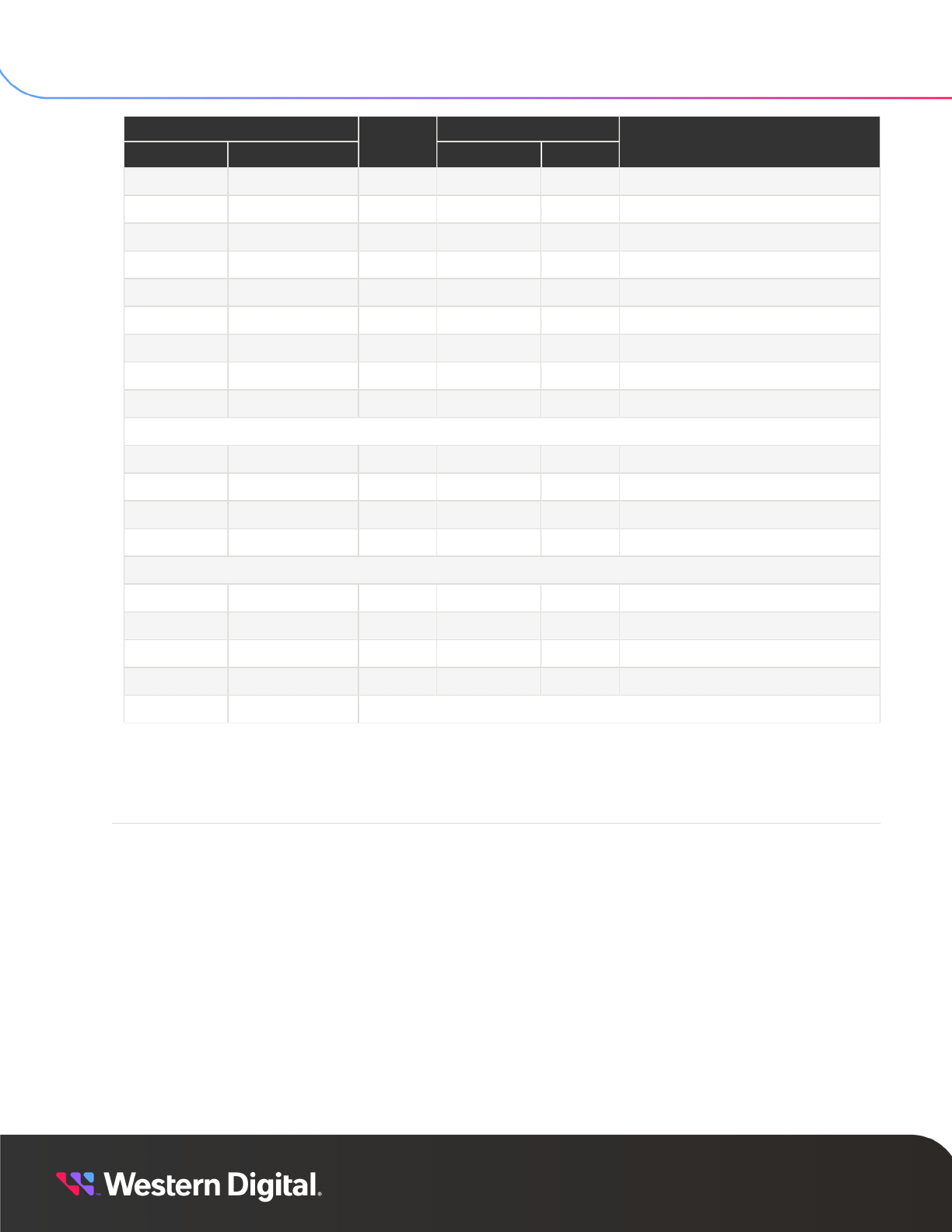
SES
Reference
4. SES Diagnostic Pages
4.10 Download Microcode Control/Status Diagnostic Page (0Eh)
Offsets Element Index
Dec Hex
Size
SG3 Abs
Description
1844 0734h 36 0,51 51 Array Slot #51
1880 0758h 36 0,52 52 Array Slot #52
1916 077Ch 36 0,53 53 Array Slot #53
1952 07A0h 36 0,54 54 Array Slot #54
1988 07C4h 36 0,55 55 Array Slot #55
2024 07E8h 36 0,56 56 Array Slot #56
2060 080Ch 36 0,57 57 Array Slot #57
2096 0830h 36 0,58 58 Array Slot #58
2132 0854h 36 0,59 59 Array Slot #59
ESCE Elements
2168 0878h 20 5,0 60 ESCE #0
2188 088Ch 20 5,1 61 ESCE #1
2208 08A0h 20 5,2 62 ESCE #2
2228 08B4h 20 5,3 63 ESCE #3
SAS Expander Elements
2248 08C8h 114 6,0 64 SAS Expander #0
2362 093Ah 152 6,1 65 SAS Expander #1
2514 09D2h 114 6,3 66 SAS Expander #3
2628 0A44h 152 6,4 67 SAS Expander #4
2780 0ADCh END OF PAGE
4.10
Download Microcode Control/Status Diagnostic Page
(0Eh)
The Download Microcode diagnostic page is used to transmit a firmware image to the enclosure services
process.
The PAGE LENGTH field indicates the number of bytes in the header block and data bytes.
The MODE field is set to the value 0Eh to indicate that a segment of firmware is being downloaded to the
SCSI Enclosure Processor (SEP). The length of the entire firmware image is in FIRMWARE IMAGE LENGTH.
The data associated with the current segment of firmware being downloaded is located in FIRMWARE
PACKET DATA, the length of the current segment is in FIRMWARE PACKET LENGTH, and the offset of the
segment is in BUFFER OFFSET. The host must send the individual segments in order of increasing BUFFER
OFFSET.
The MODE field is set to the value 0Fh to pass notification to the SEP to begin using the new firmware
image data sent by previous commands with the MODE field set to 0Eh. When the MODE field is set to 0Fh,
FIRMWARE PACKET LENGTH is expected to be 00h.
53

SES
Reference
4. SES Diagnostic Pages
4.10 Download Microcode Control/Status Diagnostic Page (0Eh)
The BUFFER ID field must always be set to 00h. The SEP code update process automatically detects the
firmware components provided in the data phase and distributes the new images to the expanders, power
supply, and so on. Drives are not updated via this mechanism. In the case of SEP code update, the enclosure
automatically distributes the received code image to all expanders in the enclosure.
The following table displays the Download Microcode Control Diagnostic page:
Table 33: Download Microcode Control Diagnostic Page
Byte/Bit 7 6 5 4 3 2 1 0
PAGE HEADER
0 00h PAGE CODE (0Eh)
1 01h SUBENCLOSURE IDENTIFIER (00h)
2 02h (MSB)
3 03h
PAGE LENGTH (n – 3)
(LSB)
DOWNLOAD MICROCODE DATA HEADER
4 04h
7 07h
EXPECTED GENERATION CODE (00000000h)
8 08h MODE (0Eh or 0Fh)
9 09h
10 0Ah
Reserved
11 0Bh BUFFER ID (00h)
12 0Ch
15 0Fh
BUFFER OFFSET (0000h – End of Image)
16 10h
19 13h
FIRMWARE IMAGE LENGTH (Total length of firmware image)
20 14h
23 17h
FIRMWARE PACKET LENGTH (Length of FIRMWARE PACKET DATA)
DOWNLOAD MICROCODE DATA
24 18h
m
FIRMWARE PACKET DATA (4096 or 8192 bytes)
m
+1
n
Pad with 00h to a multiple of 4-bytes, if needed
The following table displays the Download Microcode Status Diagnostic page:
Note: The Download Microcode status page is used to retrieve status information about the
previous download control operation.
54

SES
Reference
4. SES Diagnostic Pages
4.11 Subenclosure Nickname Control/Status Diagnostic Page (0Fh)
Table 34: Download Microcode Status Diagnostic Page
Byte/Bit 7 6 5 4 3 2 1 0
PAGE HEADER
0 00h PAGE CODE (0Eh)
1 01h NUMBER OF SECONDARY SUBENCLOSURES (00h)
2 02h
3 03h
PAGE LENGTH (14h)
DOWNLOAD MICROCODE STATUS
4 04h
7 07h
GENERATION CODE (00000000h)
8 08h Reserved
9 09h SUBENCLOSURE IDENTIFIER (00h)
10 0Ah DOWNLOAD MICROCODE STATUS
11 0Bh DOWNLOAD MICROCODE ADDITIONAL STATUS
12 0Ch
15 0Fh
DOWNLOAD MICROCODE MAXIMUM SIZE
16 10h
18 12h
Reserved
19 13h DOWNLOAD MICROCODE EXPECTED BUFFER ID
20 14h
23 17h
DOWNLOAD MICROCODE EXPECTED BUFFER OFFSET
4.11
Subenclosure Nickname Control/Status Diagnostic
Page (0Fh)
The Subenclosure Nickname page stores a text string that serves as a nickname for the specified
subenclosure. The nickname is saved to nonvolatile storage (e.g., a flash ROM) so it may be retrieved after
future hard resets.
Control Page
The following table displays the format of the Subenclosure Nickname Control Diagnostic Page:
Table 35: Subenclosure Nickname Control Diagnostic Page
Byte/Bit 7 6 5 4 3 2 1 0
0 00h PAGE CODE (0Fh)
1 01h SUBENCLOSURE IDENTIFIER
2 02h (MSB)
3 03h
PAGE LENGTH (0024h)
(LSB)
55

SES
Reference
4. SES Diagnostic Pages
4.11 Subenclosure Nickname Control/Status Diagnostic Page (0Fh)
Byte/Bit 7 6 5 4 3 2 1 0
4 04h (MSB)
...
7 07h
EXPECTED GENERATION CODE
(LSB)
8 08h
...
39 27h
SUBENCLOSURE NICKNAME
• The Subenclosure Identifier field specifies the subenclosure to which the application client is sending
the nickname.
• The Page Length field specifies the number of bytes that follow in the diagnostic page.
• The Subenclosure Nickname field specifies the subenclosure nickname.
Status Page
The following table displays the format of the Subenclosure Nickname Status Diagnostic Page:
Table 36: Subenclosure Nickname Status Diagnostic Page
Byte/Bit 7 6 5 4 3 2 1 0
0 00h PAGE CODE (0Fh)
1 01h NUMBER OF SECONDARY SUBENCLOSURES
2 02h (MSB)
3 03h
PAGE LENGTH (n - 3)
(LSB)
4 04h (MSB)
...
7 07h
GENERATION CODE
(LSB)
Subenclosure Nickname Status Descriptor List
8 08h
...
47 2Fh
Subenclosure nickname status descriptor (primary subenclosure)
(see Table 37: Subenclosure Nickname Status Descriptor (page 56))
• The Number of Secondary Subenclosures field indicates the number of secondary subenclosure
nickname status descriptor values that are included, not including the primary subenclosure.
• The Page Length field indicates the number of bytes that follow in the diagnostic page.
• The Subenclosure Nickname Status Descriptor List contains a status descriptor for each subenclosure
nickname reported.
The following table defines the format of each descriptor—the first is for the primary subenclosure, and the
rest are for secondary subenclosures.
56

SES Reference
4. SES Diagnostic Pages
4.12 Tag Data Out/In Diagnostic Page (10h)
Table 37: Subenclosure Nickname Status Descriptor
Byte/Bit 7 6 5 4 3 2 1 0
0 00h Reserved
1 01h SUBENCLOSURE IDENTIFIER
2 02h SUBENCLOSURE ENCLOSURE NICKNAME STATUS
3 03h SUBENCLOSURE ENCLOSURE NICKNAME ADDITIONAL STATUS
4 04h
5 05h
Reserved
6 06h (MSB)
7 07h
SUBENCLOSURE NICKNAME LANGUAGE CODE
(LSB)
8 08h
... ...
39 27h
SUBENCLOSURE NICKNAME
• The Subenclosure Identifier field indicates the subenclosure to which the nickname status descriptor
applies.
• The Subenclosure Nickname Status field indicates the status of nickname operations for the
subenclosure, defined in Table 38: Subenclosure Nickname Status Field (page 57).
• The Subenclosure Nickname Additional Status field provides additional status for certain values of the
Subenclosure Nickname Status field, described in Table 38: Subenclosure Nickname Status Field (page
57).
• The Subenclosure Nickname field indicates the subenclosure nickname.
Table 38: Subenclosure Nickname Status Field
Code Description
00h No errors
80h
Error in one or more of the Subenclosure Nickname Control diagnostic page fields.
The SUBENCLOSURE NICKNAME ADDITIONAL STATUS field shall be set to
the offset of the lowest byte of the field in the Subenclosure Nickname Control
diagnostic page that has an error.
81h Internal error. The nickname is lost.
82h Internal error. The previous nickname preserved.
All others Reserved
4.12
Tag Data Out/In Diagnostic Page (10h)
The Tag Data diagnostic page is a vendor unique SCSI Enclosure Services (SES) diagnostic page that
provides the host with access to a 4096 byte tag data buffer. The tag data buffer is non-volatile, and is
stored in Enclosure vital product data (VPD).
57

SES Reference
4. SES Diagnostic Pages
4.13 MiniSAS HD Cable VPD Diagnostic Page (17h)
This buffer can be written with arbitrary American Standard Code for Information Interchange (ASCII) or
hexadecimal (HEX) data. Each write to the tag data buffer, regardless of the size written, replaces the entire
contents of the tag data buffer. Writing 0 bytes, PAGE LENGTH = 3, will clear the tag data buffer.
On reads, the PAGE LENGTH will indicate the length of the tag data which has actually been stored in the
enclosure. In other words, reading the tag data buffer returns an amount of data equal to the length of the
last write to the tag data buffer, rather than the maximum size of the Tag Data region.
The following table displays the Tag Data Out/In page:
Table 39: Tag Data Out/In Diagnostic Page
Byte/Bit 7 6 5 4 3 2 1 0
PAGE HEADER
0 00h PAGE CODE (10h)
1 01h Reserved
2 02h (MSB)
3 03h
PAGE LENGTH (0 to 1000h)
(LSB)
TAG DATA
4 04h
4099 1003h
TAG DATA (0-4096 bytes)
4.13
MiniSAS HD Cable VPD Diagnostic Page (17h)
The MiniSAS HD Cable VPD Diagnostic Page is a vendor unique SES diagnostic page that provides the
host with access to the VPD information located in the MiniSAS HD host port cables. The information
provided for each port is described in the following table. The content in the individual fields are defined by
SFF-8644. If a MiniSAS HD port does not have a cable plugged into it, the corresponding fields for that port
are populated with zeros (00h) in the table below.
Table 40: MiniSAS HD Cable VPD Diagnostic Page
Byte/Bit 7 6 5 4 3 2 1 0
PAGE HEADER
0 00h PAGE CODE (17h)
1 01h Reserved
2 02h (MSB)
3 03h
PAGE LENGTH (1000h)
(LSB)
CABLE VPD DATA
4 04h MINI-SAS HD PORT A – LOWER PAGE 00 (byte 0)
... ... ...
131 83h MINI-SAS HD PORT A – LOWER PAGE 00 (byte 127)
58

SES Reference
4. SES Diagnostic Pages
4.13 MiniSAS HD Cable VPD Diagnostic Page (17h)
Byte/Bit 7 6 5 4 3 2 1 0
132 84h MINI-SAS HD PORT A – UPPER MEMORY MAP PAGE 00 (byte 0)
... ... ...
259 103h MINI-SAS HD PORT A – UPPER MEMORY MAP PAGE 00 (byte 127)
260 104h MINI-SAS HD PORT H – LOWER PAGE 00 (byte 0)
... ... ...
387 183h MINI-SAS HD PORT H – LOWER PAGE 00 (byte 127)
388 184h MINI-SAS HD PORT H – UPPER MEMORY MAP PAGE 00 (byte 0)
... ... ...
4100 1004h MINI-SAS HD PORT H – UPPER MEMORY MAP PAGE 00 (byte 127)
59

60
SES Elements
In This Chapter:
- SES Element Status Codes........................................................................................61
- Array Slot..........................................................................................................................62
- Enclosure.......................................................................................................................... 67
- Power Supply.................................................................................................................. 68
- Cooling...............................................................................................................................70
- Temperature.....................................................................................................................72
- Door.................................................................................................................................... 74
- ESCE................................................................................................................................... 75
- SAS Expander................................................................................................................. 77
- SAS Connector...............................................................................................................80
- Voltage Sensor................................................................................................................ 81
- Current Sensor............................................................................................................... 83

SES Reference
5. SES Elements
5.1 SES Element Status Codes
5.1
SES Element Status Codes
This section provides reference information for SES element types and supported element status codes.
Table 41: SES Element Types
PSU (0x02)
Encl Services Controller
Electronics (IOM) (0x7)
Array Slot (0x17)
Fan (0x03) Enclosure (0x0e) Expander (0x18)
Temperature Sensor (04) Voltage Sensor (0x12) SAS Connector (0x19)
Door (0x05) Current Sensor (0x13) —
Note: Some of the element statuses can be effected by hosts issuing Page 2 control requests.
Most of these have not been accounted for in the list of Supported Element Status Codes.
Table 42: SES Element Status Codes
Status Code Status Value
OK 1
CRITICAL 2
NONCRIT 3
UNRECOV 4
NOTINST 5
UNKNOWN 6
NOTAVAIL 7
NOACCESS 8
When the host sets a nonCrit, Crit, or unRecov bit using control page 2, the bit is marked as
FAULT_REQUESTER_SES. When the page 3 builder runs, it displays a result of "HOST" for these entries in
the page 2 header. If marked for any other reason, it will display "SES" as seen in the following example:
|Enclosure Overall Status|
NON-CRIT=1 (SES)
CRIT=1 (HOST)
There are statuses that help indicate what sets the bits on individual elements. They are displayed by the
page 3 builder and include:
Value Specification
SES set by host via page 2 control
THRESHOLD set by voltage, current or temperature threshold exceptions
SES GEN set by SES generic update on critical or non-critical state
SES ELEM set by SES element update
61

SES Reference
5. SES Elements
5.1 SES Element Status Codes
Value Specification
THERMAL set as result of thermal compromise
CONFIG set when enclosure misconfiguration has been detected
The following is an example of the status bit on an individual element:
|SES Status|
TEMP SLOT B33:Critical(THRESHOLD)
62

SES Reference
5. SES Elements
5.2 Array Slot
5.2
Array Slot
Figure 11: Physical Array Slot Layout
Note: While the enclosure supports SPC-5 compliant device reporting, the enclosure primarily
supports commands for SPC-4 compliant devices.
63

SES Reference
5. SES Elements
5.2 Array Slot
Note: RQST IDENT, PRDFAIL, DEVICE OFF, and RQST FAULT are considered persistent for
Array device fields. When these fields are set through a control request page 2, they will retain
their state through enclosure resets and drive replacements. To clear these fields when set
by page 2, another page 2 must be sent with the desired field cleared. If these fields are
set without control page 2, then they will not be persistent and will clear on reset or drive
replacement.
5.2.1
Array Device Slot Element Control and Status Elements
The following table displays the Array Device Slot Element Control information:
Table 44: Array Device Slot Element Control
Byte/Bit 7 6 5 4 3 2 1 0
COMMON CONTROL
0 00h SELECT PRDFAIL Reserved RST SWAP Reserved
1 01h RQST OK
RQST
RSVD
DEVICE
RQST HOT
SPARE
RQST
CONS
CHECK
RQST
IN CRIT
ARRAY
RQST IN
FAILED
ARRAY
RQST
REBUILD/
REMAP
RQST R/
R ABORT
2 02h
RQST
ACTIVE
DO NOT
REMOVE
Reserved
RQST
MISSING
RQST
INSERT
RQST
REMOVE
RQST
IDENT
Reserved
3 03h Reserved
RQST
FAULT
DEVICE
OFF
ENABLE
BYP A (0b)
ENABLE
BYP B (0b)
Reserved
The DEVICE OFF bit is used to power a drive off. The drive power-off operation will complete
asynchronously with respect to host initiated I/O operations to that drive or others in the array. Due to
limitations, some drive types supported by the Data60 3000 Series architecture contain a finite maximum
number of power cycles. The SCSI Enclosure Processor (SEP) will reject a DEVICE OFF request until a
minimum relaxation time has elapsed since the last DEVICE OFF request for that Array Device slot. This will
only occur if a large number of DEVICE OFF requests have been performed on that slot in the lifetime of
the drive. Should this occur, the host will be given a Check Condition with sense data indicating which Array
Device Slot Element instance requires this relaxation time.
During thermal shutdown conditions, the SEP will reject external host commands to control drive power.
Once the SEP has exited thermal shutdown state, drive power states will be automatically returned to their
prior states and future host requests to control drive power will be honored.
The following table displays the Array Device Slot Element Status:
Table 45: Array Device Slot Element Status
Byte/Bit 7 6 5 4 3 2 1 0
COMMON STATUS
0 00h Reserved PRDFAIL Reserved SWAP ELEMENT STATUS CODE
ARRAY DEVICE SLOT STATUS
1 01h OK
RSVD
DEVICE
HOT SPARE
CONS
CHECK
IN CRIT
ARRAY
IN FAILED
ARRAY
REBUILD/
REMAP
R/R ABORT
2 02h
APP
CLIENT
BYPASSED
A (0b)
DO NOT
REMOVE
ENCLOSURE
BYPASSED
A (0b)
ENCLOSURE
BYPASSED
B (0b)
READY TO
INSERT
RMV IDENT
REPORT
(0b)
64

SES Reference
5. SES Elements
5.2 Array Slot
Byte/Bit 7 6 5 4 3 2 1 0
3 03h
APP
CLIENT
BYPASSED
B (0b)
FAULT
SENSED
FAULT
REQSTD
DEVICE
OFF
BYPASSED
A (0b)
BYPASSED
B (0b)
DEVICE
BYPASSED
A (0b)
DEVICE
BYPASSED
B (0b)
The ELEMENT STATUS CODE has a value of CRITICAL to indicate that the corresponding Array Device
Slot is unable to communicate because the interconnect physical layer (PHY) has not achieved a link up
state.
The ELEMENT STATUS CODE has a value of NON-CRITICAL to indicate that the corresponding Array
Device Slot is able to communicate, but the interconnect PHY is operating at a non-optimal link rate.
The DEVICE OFF bit is true if the corresponding drive is powered off. A drive can be powered off in
response to a host sending a SES Page 2 control page, or if the enclosure autonomously powers a drive off
during a thermal offline state.
Table 46: Array Slot (0x17)
Status Code Trigger
OK Nominal
CRITICAL Array slot device PHY not linked
NONCRIT Array slot device PHY linked but not at expected rate
UNRECOV Unsupported Drive in slot
NOTINST Element not present
NOTAVAIL
• Temperature can not be read
• Array element is present but off
NOACCESS
• Element is taken offline by thermal monitor. Temperature
data also lost
• Zoning is enabled but zone group of element is not
accessible
5.2.2
Array Slot Element Descriptor
The following table displays the enclosure - Array Slot Element Descriptor information:
Note: The Location field will indicate the slot number within the enclosure. Unused bytes will
be populated with ASCII space characters.
Table 47: Data60 3000 Series - Array Slot Element Descriptor
Offsets
Dec Hex
Size Description
Header
0 00h 2 Reserved (0000h)
2 02h 2 Length (001Ch)
65

SES Reference
5. SES Elements
5.2 Array Slot
Offsets
Dec Hex
Size Description
Descriptor
4 04h 28
"SLOT NN",
<SERIAL #>
32 20h END OF DESCRIPTOR
5.2.3
Additional Element Status Descriptor
The following table displays the Additional Element Status Descriptor – Array Device Slot information:
Table 48: Additional Element Status Descriptor – Array Device Slot
Byte/
Bit
7 6 5 4 3 2 1 0
0 00h
INVALID
(0b)
Reserved EIP (1b) PROTOCOL IDENTIFIER (0110b)
1 01h ADDITIONAL ELEMENT STATUS DESCRIPTOR LENGTH (22h)
2 02h Reserved EIIO (1b)
3 03h ELEMENT INDEX
4 04h NUMBER OF PHY DESCRIPTORS (1b)
5 05h TYPE (00b) Reserved
NOT ALL
PHYS
(1b)
6 06h Reserved
7 07h DEVICE SLOT NUMBER
PHY DESCRIPTOR LIST
8 08h Reserved DEVICE TYPE Reserved
9 09h Reserved
10 0Ah Reserved
SSP
INIT (0B)
STP INIT
(0B)
SMP
INIT (0B)
Reserved
11 0Bh
SATA
PORT
SELECTOR
(0b)
Reserved
SSP
TARG
STP
TARG
(0b)
SMP
TARG
SATA
DEVICE
(0b)
12 0Ch
19 13h
ATTACHED SAS ADDRESS
20 14h
27 1Bh
SAS ADDRESS
28 1Ch PHY IDENTIFIER
66

SES Reference
5. SES Elements
5.3 Enclosure
Byte/
Bit
7 6 5 4 3 2 1 0
29 1Dh
35 23h
Reserved
The DEVICE TYPE field has the value 001b if a disk drive PHY is connected and linked at any link rate, and
the value 000b otherwise.
The SSP TARG bit has the value 1b if a disk drive PHY is connected and linked at any link rate, and the
value 0b otherwise.
5.3
Enclosure
5.3.1
Enclosure Element Control and Status
The following table displays the Enclosure Element Control information:
Note: The Data60 3000 Series architecture does not support power cycling the enclosure
via the Enclosure element type. The capability to perform enclosure resets is provided in the
String Out/In Diagnostic Page (04h) (page 40) section.
Table 49: Enclosure Element Control
Byte/Bit 7 6 5 4 3 2 1 0
COMMON CONTROL
0 00h SELECT PRDFAIL Reserved RST SWAP Reserved
ENCLOSURE CONTROL
1 01h
REQUEST
IDENT
Reserved
2 02h
POWER CYCLE
REQUEST (00b)
POWER CYCLE DELAY (000000b)
3 03h POWER OFF DURATION (000000b)
REQUEST
FAIL
REQUEST
WARNING
The following table displays the Enclosure Element Status information:
Table 50: Enclosure Element Status
Byte/Bit 7 6 5 4 3 2 1 0
COMMON STATUS
0 00h Reserved PRDFAIL Reserved SWAP ELEMENT STATUS CODE
ENCLOSURE STATUS
1 01h IDENT Reserved
2 02h TIME UNTIL POWER CYCLE (000000b)
FAILURE
INDICATION
WARNING
INDICATION
3 03h POWER OFF DURATION (000000b)
FAILURE
REQUESTED
WARNING
REQUESTED
67

SES Reference
5. SES Elements
5.3 Enclosure
The SCSI Enclosure Processor (SEP) does not support host requests to power cycle or power off the
enclosure.
The FAILURE INDICATION and WARNING INDICATION bits are only set to indicate failure and warning
conditions which are requested by hosts by sending an Enclosure Element Control block. The WARNING
INDICATION bit is set to 1 to indicate that either the PRDFAIL or the WARNING REQUESTED bits in the
Enclosure Element Control block was set.
The FAILURE INDICATION and WARNING INDICATION bits do not serve as failure and warning summary
bits for conditions that may exist in other element instances within the enclosure. The CRIT and NON
CRIT bits in byte 1 of Enclosure Status Diagnostic page header indicate if any element instance within the
enclosure is being reported with a critical or non-critical condition.
Table 51: Enclosure (0x0e)
Status Code Trigger
OK Nominal
CRITICAL
• Thermal compromise
• IOM missing in dual IOM enclosure
NONCRIT rqstWarn from HOST
NOTINST Element not present
5.3.2
Enclosure Element Descriptor
The following table displays the enclosure - Enclosure Element Descriptor information:
Note: The VPD version contains a two byte ASCII value indicating the version of the VPD data.
Unused bytes are populated with ASCII space characters.
Table 52: Data60 3000 Series - Array Slot Element Descriptor
Offsets
Dec Hex
Size Description
Header
0 00h 2 Reserved(0000h)
2 02h 2 Length (007Ch)
Descriptor
4 04h 28
"ENCLOSURE",
<ENC PART #>,
<ENC SERIAL #>,
<BRD Part #>,
<BRD Serial #>
128 80h END OF DESCRIPTOR
68

SES Reference
5. SES Elements
5.4 Power Supply
5.4
Power Supply
The Location field value will be set to a 16 byte ASCII string that describes the instance of the power supply.
Unused bytes will be filled with ASCII space characters.
The Part Number and Serial Number fields will be blank (ASCII space characters) for missing or not installed
power supplies. The Location field will always be reported, even if the power supply is not installed.
5.4.1
Power Supply Element Control and Status
The following table displays the Power Supply Element Control information:
Table 53: Power Supply Element Control
Byte/Bit 7 6 5 4 3 2 1 0
COMMON CONTROL
0 00h SELECT PRDFAIL Reserved RST SWAP Reserved
POWER SUPPLY CONTROL
1 01h
REQUEST
IDENT
DO NOT
REMOVE
(0b)
Reserved
2 02h Reserved
3 03h Reserved RQST FAIL
RQST
ON (1b)
Reserved
Table 54: Power Supply Element Status
Byte/Bit 7 6 5 4 3 2 1 0
COMMON STATUS
0 00h Reserved PRDFAIL Reserved SWAP ELEMENT STATUS CODE
POWER SUPPLY STATUS
1 01h
RQST
IDENT
DO NOT
REMOVE
Reserved
2 02h Reserved
DC OVER
VOLTAGE
DC UNDER
VOLTAGE
DC OVER
CURRENT
Reserved
3 03h HOT SWAP FAIL
RQSTED
ON (1b)
OFF (0b)
OVERTEMP
FAIL
TEMP
WARN
AC FAIL DC FAIL
The SCSI Enclosure Processor (SEP) does not support host requests to turn off power supplies.
The DO NOT REMOVE bit is set to one when the HOT SWAP bit is set to zero, and is set to zero when the
HOT SWAP bit is set to one.
The HOT SWAP bit reports the value 1b if the reported power supply instance may be inserted or removed
without powering off the enclosure. The HOT SWAP bit will be set to 1b in either of the following instances:
• The power supply is not installed
• The power supply is installed, and the partner power supply is installed, powered on, and its Element
Status Code is OK (01h)
69

SES Reference
5. SES Elements
5.4 Power Supply
Table 55: PSU (0x02)
Status Code Trigger
OK Nominal
CRITICAL
• PMBus: DC over volt
• PMBus: DC under volt
• PMBus: DC over current
• PMBus: Temperature fail
• PMBus: AC fail
• PMBus: PSU off
• PMBus: DC fail
Note: PMBus == PMBus
STATUS_WORD bit derivatives
NONCRIT PMBus: Temperature warn
NOTINST Element not present
UNKNOWN Lost I2C communications
5.4.2
Power Supply Element Descriptor
The following table displays the Enclosure - Power Supply Element Descriptor information:
Note: The Location field value will be set to a 16 byte ASCII string that describes the instance
of the power supply. Unused bytes will be populated with ASCII space characters.
Table 56: Enclosure - Power Supply Element Descriptor
Offsets
w/o MFC With MFC
Dec Hex Dec Hex
Size Description
0 0000h 0 0000h 2 Reserved (0000h)
2 0002h 2 0002h 2 Descriptor Length (0042h/0062)
4 0004h 4 0004h 16 Location (POWER SUPPLY N)
20 0014h 20 0014h 16 Part Number ()
36 0024h 36 0024h 18 Serial Number ()
54 0036h 54 0036h 16 Firmware Revision ()
70 0046h 32 Power Supply MFC
70 0046h 102 0066h END OF DESCRIPTOR
70

SES Reference
5. SES Elements
5.5 Cooling
5.5
Cooling
The Location field value will be set to a 16 byte ASCII string that describes the instance of the fan. Unused
bytes will be filled with ASCII space characters.
All fields will remain, even if a fan is not installed, since the Part Number and Serial Number come from the
fan controller which is not removed when replacing a fan.
5.5.1
Rear Fan Cooling Element Control and Status
The following table displays the Cooling (Fan) Element Control information:
Table 57: Cooling (Fan) Element Control
Byte/Bit 7 6 5 4 3 2 1 0
COMMON CONTROL
0 00h SELECT PRDFAIL Reserved
RST
SWAP
Reserved
COOLING (FAN) CONTROL
1 01h
REQUEST
IDENT
DO NOT
REMOVE
(0b)
Reserved
2 02h Reserved
3 03h Reserved RQST FAIL
RQST
ON (1b)
Reserved REQUESTED SPEED CODE (000b)
The following table displays the Cooling (Fan) Element Status information:
Note: The SEP does not support host requests to turn off cooling elements or to manually set
a requested fan speed.
Table 58: Cooling (Fan) Element Status
Byte/Bit 7 6 5 4 3 2 1 0
COMMON STATUS
0 00h Reserved PRDFAIL Reserved SWAP ELEMENT STATUS CODE
COOLING FAN STATUS
1 01h IDENT
DO NOT
REMOVE
(0b)
Reserved (MSB)
2 02h ACTUAL FAN SPEED (LSB)
3 03h
HOT
SWAP (1b)
FAIL
RQSTED
ON (1b)
OFF Reserved ACTUAL SPEED CODE
The ELEMENT STATUS CODE can report a value of CRITICAL to indicate that one or more fans are not
spinning as fast as they are expected to.
The ACTUAL FAN SPEED field reports the current fan speed in units of 10 RPM. For example, the value
300h would be reported to indicate a fan speed of 7680 RPM.
71

SES Reference
5. SES Elements
5.5 Cooling
The HOT SWAP bit has the value 1b, if fans can be swapped without requiring or causing a power cycle
event.
The OFF bit is set to indicate that the corresponding fan is not operating.
Table 59: Fan (0x03)
Status Code Trigger
OK Nominal
CRITICAL Fan failed
NOTINST Element not present
UNKNOWN Lost I2C communications
OK Nominal
CRITICAL Temperature over/under critical threshold
NONCRIT Temperature over/under warning threshold
NOTINST Element not present
UNKNOWN Lost I2C communications
NOTAVAIL Sensor can not be read successfully
NOACCESS
Corresponding array element was taken offline by thermal
monitor, access to temperature data lost
5.5.2
Cooling Element Descriptor
The following table displays the Enclosure - Cooling (Rear Fans) Element Descriptor information:
Note: The Location field value will be set to a 16 byte ASCII string that describes the instance
of the fan. Unused bytes will be populated with ASCII space characters.
Table 60: Enclosure - Cooling (Rear Fans) Element Descriptor
Offsets
w/o MFC With MFC
Dec Hex Dec Hex
Size Description
0 0000h 0 0000h 2 Reserved (0000h)
2 0002h 2 0002h 2
Descriptor Length
(0030h/006Ah)
4 0004h 4 0004h 16 Location (PSU N FAN N)
20 0014h 20 0014h 16 Part Number
36 0024h 36 0024h 16 Serial Number
52 0034h 58 Cooling MFC
52 0034h 110 006Eh END OF DESCRIPTOR
72

SES Reference
5. SES Elements
5.6 Temperature
5.6
Temperature
The Location field value will be set to a 16 byte ASCII string that describes the instance of the temperature
sensor. Unused bytes will be filled with ASCII space characters.
5.6.1
Temperature Sensor Element Control and Status
The following table displays the Temperature Sensor Element Control information:
Note: The Data60 3000 Series architecture does not support power cycling the enclosure
via the Enclosure element type. The capability to perform enclosure resets is provided in the
String Out/In Diagnostic Page (04h) (page 40) section.
Table 61: Temperature Sensor Element Control
Byte/Bit 7 6 5 4 3 2 1 0
COMMON CONTROL
0 00h SELECT PRDFAIL
DISABLE
(0b)
RST
SWAP
Reserved
TEMPERATURE SENSOR CONTROL
1 01h
REQUEST
IDENT
REQUEST
FAIL
Reserved
2 02h Reserved
3 03h Reserved
Note: The SCSI Enclosure Processor (SEP) does not support host requests to disable
temperature sensors.
The following table displays the Temperature Sensor Element Status information:
Table 62: Temperature Sensor Element Status
Byte/Bit 7 6 5 4 3 2 1 0
COMMON STATUS
0 00h Reserved PRDFAIL
DISABLED
(0b)
SWAP ELEMENT STATUS CODE
TEMPERATURE SENSOR STATUS
1 01h IDENT FAIL Reserved
2 02h TEMPERATURE
3 03h Reserved
OT
FAILURE
OT
WARNING
UT
FAILURE
UT
WARNING
The TEMPERATURE field reports the current temperature in units of degrees Celsius offset by 20.For
example, a value of 40h, or 64 decimal, is used to report an actual temperature of 44 degrees Celsius.
73

SES Reference
5. SES Elements
5.7 Door
The OT/UT FAILURE or OT/UT WARNING bits are set if a temperature sensor is reporting a value that
exceeds the corresponding critical or warning threshold values defined by the default Vital Product Data
(VPD) based thresholds as modified by the Threshold Out page. The thresholds in current use may be
discovered by using the Threshold In Diagnostic page.
Temperature sensors which are located on drives are polled less often than temperature sensors located
on other components. This is to minimize the impact of SCSI Enclosure Processor (SEP) initiated polling on
host initiated I/Os.
Table 63: Temperature Sensor (04)
Status Code Trigger
OK Nominal
CRITICAL Temperature over/under critical threshold
NONCRIT Temperature over/under warning threshold
NOTINST Element not present
UNKNOWN Lost I2C communications
NOTAVAIL Sensor can not be read successfully
NOACCESS
Corresponding array element was taken offline by thermal
monitor, access to temperature data lost
5.6.2
Temperature Element Descriptor
The following table displays the Enclosure - Temperature Element Descriptor information:
Table 64: Enclosure - Temperature Element Descriptor
Offsets
Dec Hex
Size Description
0 0000h 2 Reserved (0000h)
2 0002h 2 Descriptor Length (0010h)
4 0004h 16 Location (TEMP<location>)
20 0014h END OF DESCRIPTOR
5.7
Door
The Location field value will be set to a 16 byte ASCII string that describes the instance of the door. Unused
bytes will be filled with ASCII space characters.
5.7.1
Door Element Control and Status
In the Data60 3000 Series architecture, the Door element manages a door.
The following table displays the Door information:
74

SES Reference
5. SES Elements
5.7 Door
Table 65: Door Element Control
Byte/Bit 7 6 5 4 3 2 1 0
COMMON CONTROL
0 00h SELECT PRDFAIL
DISABLE
(0b)
RST SWAP Reserved
DOOR CONTROL
1 01h
REQUEST
IDENT
RQST FAIL Reserved
2 02h Reserved
3 03h Reserved UNLOCK(01b)
The following table displays the Door Element Status information:
Table 66: Door Element Status
Byte/Bit 7 6 5 4 3 2 1 0
COMMON STATUS
0 00h Reserved PRDFAIL
DISABLED
(0b)
SWAP ELEMENT STATUS CODE
DOOR STATUS
1 01h IDENT FAIL RESERVED
2 02h RESERVED
3 03h RESERVED OPEN UNLOCKED(01b)
Table 67: Door (0x5)
Status Code Trigger
OK Nominal
CRITICAL Door switch open
5.7.2
Door Element Descriptor
The following table displays the Door Element Descriptor information:
Table 68: Door Element Descriptor
Offsets
Dec Hex
Size Description
0 0000h 2 Reserved (0000h)
2 0002h 2 Descriptor Length (0010h)
4 0004h 16 Location (ENCLOSURE COVER)
20 0014h END OF DESCRIPTOR
75

SES Reference
5. SES Elements
5.8 ESCE
5.8
ESCE
The Location field value will be set to IOM. Unused bytes will be populated with ASCII space characters.
5.8.1
Enclosure Services Controller Electronics Element Control
and Status
In the Data60 3000 Series architecture, the Enclosure Services Controller Electronics (ESCE) element type
is used to represent the input/output module (IOM) or host expander module (HEM).
The following table displays the Enclosure Services Controller Electronics Element Control information:
Table 69: Enclosure Services Controller Electronics Element Control
Byte/Bit 7 6 5 4 3 2 1 0
COMMON CONTROL
0 00h SELECT PRDFAIL Reserved RST SWAP Reserved
ENCLOSURE SERVICES CONTROLLER ELECTRONICS CONTROL
1 01h
RQST
IDENT
RQST
FAIL
DO NOT
REMOVE (0b)
RQST
REMOVE (0b)
Reserved
2 02h Reserved
SELECT
ELEMENT
(0b)
3 03h Reserved
Note: The SEP does not support host requests to assign the active enclosure services
processor.
The following table displays the Enclosure Services Controller Electronics information:
Table 70: Enclosure Services Controller Electronics Element Status
Byte/Bit 7 6 5 4 3 2 1 0
COMMON STATUS
0 00h Reserved PRDFAIL Reserved SWAP ELEMENT STATUS CODE
ENCLOSURE SERVICES CONTROLLER ELECTRONICS STATUS
1 01h IDENT FAIL
DO NOT
REMOVE
RMV Reserved
2 02h Reserved REPORT
3 03h
Dual ESM: HOT
SWAP (1b)
Single ESM:
HOT SWAP (0b)
The ELEMENT STATUS CODE can report a value of CRITICAL to indicate that one or more firmware
revisions within the I/O Module (IOM) are incompatible with each other.
A DO NOT REMOVE bit set to one to indicate that the ESCE should not be removed. A DO NOT REMOVE
bit set to zero to indicate that the ESCE may be removed.
76

SES Reference
5. SES Elements
5.8 ESCE
The RMV bit is set to 0 in non-redundant IOM configurations, and is set to 1 in redundant IOM
configurations.
Table 71: Encl Services Controller Electronics (IOM) (0x7)
Status Code Trigger
OK Nominal
CRITICAL
• Incompatible firmware revisions detected
• OOBM communications lost (if configured)
• IOM A missing in a dual enclosure
• IOM B missing in a dual enclosure
NOTINST Element not present
NOTAVAIL When Single Tenant, element not present
NOACCESS When Single Tenant, dual is not enabled and running on IOM B
5.8.2
Additional Element Status Descriptor—ESCE
The following table displays the Additional Element Status Descriptor – ESCE information:
Table 72: Additional Element Status Descriptor – ESCE
Byte/
Bit
7 6 5 4 3 2 1 0
0 00h INVALID Reserved EIP (1b) PROTOCOL IDENTIFIER (0110b)
1 01h ADDITIONAL ELEMENT STATUS DESCRIPTOR LENGTH (12h)
2 02h Reserved EIIOE (01b)
3 03h ELEMENT INDEX
4 04h NUMBER OF PHY DESCRIPTORS (01h)
5 05h TYPE (01b) Reserved
6 06h
7 07h
Reserved
8 08h PHY IDENTIFIER
9 09h Reserved
10 0Ah CONNECTOR ELEMENT INDEX
11 0Bh OTHER ELEMENT INDEX
12 0Ch
13 13h
SAS ADDRESS
77

SES Reference
5. SES Elements
5.9 SAS Expander
5.9
SAS Expander
The Location field value will be set to a 16 byte ASCII string that describes the instance of the SAS
expander. Unused bytes will be filled with ASCII space characters.
5.9.1
SAS Expander Element Control and Status
The following table displays the SAS (SAS) Expander Element Control information:
Table 73: SAS Expander Element Control
Byte/
Bit
7 6 5 4 3 2 1 0
COMMON CONTROL
0 00h SELECT PRDFAIL Reserved
RST
SWAP
Reserved
SAS EXPANDER CONTROL
1 01h
REQUEST
IDENT
REQUEST
FAIL
Reserved
2 02h Reserved
3 03h Reserved
The following table displays the SAS Expander Element Status information:
Table 74: SAS Expander Element Status
Byte/
Bit
7 6 5 4 3 2 1 0
COMMON STATUS
0 00h Reserved PRDFAIL Reserved SWAP ELEMENT STATUS CODE
SAS EXPANDER STATUS
1 01h IDENT FAIL Reserved
2 02h
3 03h
Reserved
The ELEMENT STATUS CODE can report a value of CRITICAL to indicate that the corresponding SAS
Expander is unable to communicate with the other SAS Expanders in the SCSI Enclosure Processor (SEP).
The ELEMENT STATUS CODE can report a value of NON-CRITICAL to indicate that one or more PHYs
used to interconnect SAS Expanders within the SEP are not up, or are not operating at the optimal physical
link rate.
Table 75: Expander (0x18)
Status Code Trigger
OK Nominal
78

SES Reference
5. SES Elements
5.9 SAS Expander
Status Code Trigger
NOTINST Element is not present
5.9.2
SAS Expander Element Descriptor
The following table displays the Enclosure - SAS Expander Element Descriptor information:
Table 76: Enclosure - SAS Expander Element Descriptor
Offsets
Dec Hex
Size Description
0 0000h 2 Reserved (0000h)
2 0002h 2 Descriptor Length (0030h)
4 0004h 16 Location (EXP <expander>)
20 0014h 16 Firmware Revision (XXXX-YYY)
36 0024h 16 Init String Revision (XXXX-YYY)
52 0034h END OF DESCRIPTOR
5.9.3
Additional Element Status Descriptor—SAS Expander
The following table displays the Additional Element Status Descriptor – SAS Expander (68 port)
information:
Table 77: Additional Element Status Descriptor – 68 Port SAS Expander
Byte/
Bit
7 6 5 4 3 2 1 0
0 00h INVALID Reserved EIP (1b) PROTOCOL IDENTIFIER (0110b)
1 01h ADDITIONAL ELEMENT STATUS DESCRIPTOR LENGTH (96h)
2 02h Reserved EIIO (1b)
3 03h ELEMENT INDEX
4 04h NUMBER OF PHY DESCRIPTORS
5 05h TYPE (01b) Reserved
6 06h
7 07h
Reserved
8 08h
15 0Fh
SAS Address
EXPANDER PHY DESCRIPTOR LIST
16 10h CONNECTOR ELEMENT INDEX #1
17 11h OTHER ELEMENT INDEX #1
... ... ...
79

SES Reference
5. SES Elements
5.10 SAS Connector
Byte/
Bit
7 6 5 4 3 2 1 0
150 96h CONNECTOR ELEMENT INDEX #68
151 97h OTHER ELEMENT INDEX #68
5.10
SAS Connector
The Location field value will be set to a 16 byte ASCII string that describes the instance of the SAS
connector. Unused bytes will be populated with ASCII space characters.
5.10.1
SAS Connector Element Control and Status
In the Data60 3000 Series architecture, the SAS Connector element type is used to represent both
SAS host port connections within the enclosure, and SAS expansion port connections that lead to other
enclosures.
The following table displays the SAS Connector Element Control information:
Table 78: SAS Connector Element Control
Byte/Bit 7 6 5 4 3 2 1 0
COMMON CONTROL
0 00h SELECT PRDFAIL Reserved RST SWAP Reserved
SAS CONNECTOR CONTROL
1 01h
REQUEST
IDENT
Reserved
2 02h Reserved
3 03h Reserved
REQUEST
FAIL
Reserved
The following table displays the SAS Connector Element Status information:
Table 79: SAS Connector Element Status
Byte/
Bit
7 6 5 4 3 2 1 0
COMMON STATUS
0 00h Reserved PRDFAIL Reserved SWAP ELEMENT STATUS CODE
SAS CONNECTOR STATUS
1 01h IDENT CONNECTOR TYPE
2 02h CONNECTOR PHYSICAL LINK
3 03h MATED FAIL OC (0b) Reserved
The ELEMENT STATUS CODE has a value of CRITICAL to indicate that the corresponding SAS Connector
has a cable inserted but is unable to communicate because none of the PHYs on the port have achieved a
link up state.
80

SES Reference
5. SES Elements
5.11 Voltage Sensor
The ELEMENT STATUS CODE has a value of NON-CRITICAL to indicate that the corresponding SAS
Connector has a cable inserted and is able to communicate, but one or more PHYs on the port have not
achieved a link up state, or the PHYs within the port that have achieved a link up state are using different
link rates.
Table 80: SAS Connector (0x19)
Status Code Trigger
OK Nominal
CRITICAL
• If active cable detected and cable configuration is invalid
• No PHY on host port is linked
NONCRIT
• Dual IOM is not configured and running on IOM B
• Host port has < 4 PHYs linked
• Host port has PHY link mismatches
NOTINST
• Connector not present
• Connector present but cable not plugged in
5.10.2
SAS Connector Element Descriptor
The following table displays the Enclosure - Serial Attached SCSI (SAS) Connector Element Descriptor
information:
Table 81: Enclosure - SAS Connector Element Descriptor
Offsets
Dec Hex
Size Description
0 0000h 2 Reserved (0000h)
2 0002h 2 Descriptor Length (0010h)
4 0004h 16 Location (CONN HOST X)
20 0014h END OF DESCRIPTOR
5.11
Voltage Sensor
The Location field value will be set to a 16 byte ASCII string that describes the instance of the voltage
sensor. Unused bytes will be populated with ASCII space characters.
5.11.1
Voltage Sensor Element Control and Status
The following table displays the Voltage Sensor Element Control information:
81
SES Reference
5. SES Elements
5.11 Voltage Sensor
Table 82: Voltage Sensor Element Control
Byte/
Bit
7 6 5 4 3 2 1 0
COMMON CONTROL
0 00h SELECT PRDFAIL
DISABLED
(0b)
RST
SWAP
Reserved
VOLTAGE SENSOR CONTROL
1 01h
REQUEST
IDENT
REQUEST
FAIL
Reserved
2 02h Reserved
3 03h Reserved
Note: The SEP does not support host requests to disable voltage sensors.
The following table displays the Voltage Sensor Element Status information:
Table 83: Voltage Sensor Element Status
Byte/
Bit
7 6 5 4 3 2 1 0
COMMON STATUS
0 00h Reserved PRDFAIL
DISABLED
(0b)
SWAP ELEMENT STATUS CODE
VOLTAGE SENSOR STATUS
1 01h IDENT FAIL Reserved
WARN
OVER
WARN
UNDER
CRIT
OVER
CRIT
UNDER
2 02h (MSB)
3 03h
VOLTAGE
(LSB)
The VOLTAGE field reports the current voltage in units of 10 millivolts. For example, the value 200h would
be reported to indicate a voltage of 5120 millivolts.
Table 84: Voltage Sensor (0x12)
Status Code Trigger
OK Nominal
CRITICAL Over/under critical threshold
NONCRIT Over/under warning threshold
NOTINST Element not present
UNKNOWN Lost I2C communications
82

SES Reference
5. SES Elements
5.12 Current Sensor
5.11.2
Voltage Sensor Element Descriptor
The following table displays the Enclosure - Voltage Element Descriptor information:
Table 85: Enclosure - Voltage Element Descriptor
Offsets
Dec Hex
Size Description
0 0000h 2 Reserved (0000h)
2 0002h 2 Descriptor Length (0010h)
4 0004h 16 Location (XXXV <name>)
20 0014h END OF DESCRIPTOR
5.12
Current Sensor
The Location field value will be set to a 16 byte ASCII string that describes the instance of the current
sensor. Unused bytes will be populated with ASCII space characters.
5.12.1
Current Sensor Element Control and Status
The following table displays the Current Sensor Element Control information:
Table 86: Current Sensor Element Control
Byte/
Bit
7 6 5 4 3 2 1 0
COMMON CONTROL
0 00h SELECT PRDFAIL
DISABLED
(0b)
RST
SWAP
Reserved
CURRENT SENSOR CONTROL
1 01h
REQUEST
IDENT
REQUEST
FAIL
Reserved
2 02h Reserved
3 03h Reserved
Note: The SEP does not support host requests to disable current sensors.
The following table displays the Current Element Status information:
Table 87: Current Sensor Element Status
Byte/
Bit
7 6 5 4 3 2 1 0
COMMON STATUS
83

SES Reference
5. SES Elements
5.12 Current Sensor
Byte/
Bit
7 6 5 4 3 2 1 0
0 00h Reserved PRDFAIL
DISABLED
(0b)
SWAP ELEMENT STATUS CODE
CURRENT STATUS
1 01h IDENT FAIL Reserved
WARN
OVER
Reserved
CRIT
OVER
Reserved
2 02h (MSB)
3 03h
CURRENT
(LSB)
The CURRENT field reports the current in units of 10 milliamps. For example, the value 200h would be
reported to indicate a current of 5120 milliamps.
Table 88: Current Sensor (0x13)
Status Code Trigger
OK Nominal
CRITICAL Over/under critical threshold
NONCRIT Over/under warning threshold
NOTINST Element not present
UNKNOWN Lost I2C communications
5.12.2
Current Sensor Element Descriptor
The following table displays the Enclosure - Current Element Descriptor information:
Table 89: Enclosure - Current Element Descriptor
Offsets
Dec Hex
Size Description
0 0000h 2 Reserved (0000h)
2 0002h 2 Descriptor Length (0010h)
4 0004h 16 Location (CURRENT <name>)
20 0014h END OF DESCRIPTOR
84

85
SCSI Commands
In This Chapter:
- SEP SCSI Behavior Overview................................................................................... 86
- Test Unit Ready............................................................................................................. 86
- Request Sense................................................................................................................87
- Inquiry.................................................................................................................................87

SES Reference
6. SCSI Commands
6.1 SEP SCSI Behavior Overview
6.1
SEP SCSI Behavior Overview
The following section describes the generic SCSI behavior of the SEP:
• SEP supports up to four concurrent initiators
• SEP does not support SCSI command linking or queue tags
• SEP operates with a command Queue Depth of one per host
•
All commands are processed in FIFO order
Note: The exception is Task Management commands (for example, Abort Task, and so on.)
The following table lists the SCSI commands supported by the SCSI Enclosure Processor (SEP):
Table 90: Supported SCSI Commands
Command Name Op Code Reference
TEST UNIT READY 00h SPC-4
INQUIRY 12h SPC-4
REQUEST SENSE 03h SPC-4
SEND DIAGNOSTIC 1Dh SPC-4
RECEIVE DIAGNOSTIC RESULTS 1Ch SPC-4
REPORT LUNS 10h SPC-4
MODE SELECT (10) 55h SPC-4
MODE SENSE (10) 5Ah SPC-4
LOG SELECT 4Ch SPC-4
LOG SENSE 4Dh SPC-4
6.2
Test Unit Ready
The following table displays the Test Unit Ready commands:
Table 91: Test Unit Ready
Byte/
Bit
7 6 5 4 3 2 1 0
0 00h OPERATION CODE (00h)
1 01h
4 04h
Reserved
5 05h CONTROL (00h)
The TEST UNIT READY command requests that the device server indicates if the logical unit is ready. If the
SEP is able to accept SES page commands without returning CHECK CONDITION status, then the SEP shall
complete the command with a GOOD status. If the SEP is nonoperational, the device server shall terminate
the command with a CHECK CONDITION status, with the sense key set to NOT READY.
86

SES Reference
6. SCSI Commands
6.3 Request Sense
Note: The Data60 3000 Series SEP can enter an offline state in which SEP remains available,
but the disk drives are not presented to hosts. Because the SEP remains available, the SEP will
return a SCSI GOOD status in response to TEST UNIT READY even if it is in offline state.
6.3
Request Sense
The REQUEST SENSE command requests that the SEP return sense data in the data phase of the
operation. It is seldom used because SAS provides auto-sense in the response frame following the
completion of each SCSI command.
The following table displays the Request Sense commands:
Table 92: Request Sense Command
Byte/
Bit
7 6 5 4 3 2 1 0
0 00h OPERATION CODE (03h)
1 01h Reserved
DESC
(0b)
2 02h Reserved
3 03h Reserved
4 04h ALLOCATION LENGTH
5 05h CONTROL (00h)
6.4
Inquiry
The INQUIRY command requests the SEP to return information regarding the logical unit and SCSI target
device.
The following table displays the Inquiry commands:
Table 93: Inquiry Command
Byte/
Bit
7 6 5 4 3 2 1 0
0 00h OPERATION CODE (12h)
1 01h Reserved Obsolete EVPD
2 02h PAGE CODE
3 03h (MSB)
4 04h
ALLOCATION LENGTH
(LSB)
5 05h CONTROL (00h)
87

SES Reference
6. SCSI Commands
6.4 Inquiry
EVPD bit set to 0 specifies that the logical unit shall return the standard INQUIRY data. If the PAGE CODE
field is not set to 0 and the EVPD bit is set to 0, then the command will terminate with CHECK CONDITION
status, with the sense key set to ILLEGAL REQUEST, and the additional sense code set to INVALID
FIELD IN CDB. If the EVPD bit is set to 1, the PAGE CODE field specifies which page of vital product data
information the logical unit shall return. If the page code is not implemented by the logical unit the command
will terminate with CHECK CONDITION status, with the sense key set to ILLEGAL REQUEST, and the
additional sense code set to INVALID FIELD IN CDB.
6.4.1
Standard INQUIRY Data
The following table displays the Standard Inquiry commands:
Table 94: Standard Inquiry Command
Byte/Bit 7 6 5 4 3 2 1 0
0 00h PERIPHERAL QUALIFIER (000b) PERIPHERAL DEVICE TYPE (0Dh)
1 01h RMB (0b)
LU_CONG
(0b)
Reserved
2 02h VERSION (06h)
3 03h Reserved Reserved
NormACA
(0b)
HiSup (0b) Response Data Format (2h)
4 04h ADDITIONAL LENGTH (5Bh)
5 05h SCCS (0b) ACC (0b) TPGS (00b) 3PC (0b) Reserved
PROTECT
(0b)
6 06h Reserved
EncServ
(1b)
VS (0b) MultiP (0b) Reserved Reserved Reserved
ADDR16
(0b)
7 07h Reserved Reserved
WBUS16
(0b)
SYNC (0b) Reserved Reserved
CMDQUE
(1b)
VS (0b)
8 08h
15 0Fh
VENDOR IDENTIFICATION
16 10h
31 1Fh
PRODUCT IDENTIFICATION
32 20h
35 23h
PRODUCT REVISION (FIRMWARE REV)
36 24h
55 37h
DETAILED FIRMWARE REVISION
56 38h
57 39h
Reserved
58 3Ah
59 3Bh
VERSION DESCRIPTOR: SAM-5 (00A0h)
60 3Ch
61 3Dh
VERSION DESCRIPTOR: SAS-2 (0C20h)
62 3Eh
63 3Fh
VERSION DESCRIPTOR: SPC-5 (0460 => 05C0, 0580=>0584)
64 40h
65 41h
VERSION DESCRIPTOR: SES-3 (0580h)
66 42h
Reserved(00h)
88

SES Reference
6. SCSI Commands
6.4 Inquiry
Byte/Bit 7 6 5 4 3 2 1 0
95 5Fh
The VENDOR IDENTIFICATION command contains an 8 byte ASCII string that reports the vendor name.
This string is left justified in the field and is not NULL terminated. The string that is reported is defined by
enclosure VPD.
The PRODUCT IDENTIFICATION command contains a 16 byte ASCII string that reports the product name.
The string is left justified in the field and is not NULL terminated. The string that is reported is defined by
enclosure VPD.
The PRODUCT REVISION command contains a 4 bytes which indicate the firmware revision information.
In the released code images, each of the 4 bytes is an ASCII encoded decimal digit. The first 2 bytes
represent the release major number, and the second 2 bytes represent the release minor number. In the
unreleased code images, the first byte of the PRODUCT REVISION field will contain something other than
an ASCII encoded decimal digit.
The DETAILED FIRMWARE REVISION command contains an ASCII string that represents the full SEP
product firmware revision. The information is left justified within the field, and is padded with spaces.
The following is the format breakdown of -BBB MM.mm.rr:
• BBB: 3 digit decimal build number
• MM: is the major revision number of the firmware framework
• mm: is the minor revision number of the firmware framework
• rr: is the sub-minor revision number of the firmware framework
6.4.2
Supported INQUIRY Vital Product Pages
The following table displays the Supported INQUIRY VPD pages:
Table 95: Supported INQUIRY VPD Pages
VPD Page Name Page Code
Supported VPD Pages 00h
Unit Serial Number 80h
Device Identification 83h
Extended INQUIRY Data 86h
SEP Capabilities C1h
Note: These VPD pages are returned by an INQUIRY command with the EVPD bit set to one,
and contain product information about the SEP.
6.4.2.1
Supported VPD Pages (00h)
The following table displays the Supported VPD pages:
89

SES Reference
6. SCSI Commands
6.4 Inquiry
Table 96: Supported VPD Pages
Byte/
Bit
7 6 5 4 3 2 1 0
0 00h
PERIPHERAL
QUALIFIER (000b)
PERIPHERAL DEVICE TYPE (0Dh)
1 01h PAGE CODE (00h)
2 02h (MSB)
3 03h
PAGE LENGTH (05h)
(LSB)
SUPPORTED VPD PAGE LIST
4 04h SUPPORTED VPD PAGES (00h)
5 05h UNIT SERIAL NUMBER (80h)
6 06h DEVICE IDENTIFICATION (83h)
7 07h EXTENDED INQUIRY DATA (86h)
8 08h SEP CAPABILITIES (C1h)
Note: The Supported VPD Pages VPD page contains a list of the Inquiry VPD page codes
supported by the SEP.
6.4.2.2
Unit Serial Number VPD Pages (80h)
The following table displays the Unit Serial Number VPD page:
Table 97: Unit Serial Number VPD Page
Byte/
Bit
7 6 5 4 3 2 1 0
0 00h
PERIPHERAL
QUALIFIER (000b)
PERIPHERAL DEVICE TYPE (0Dh)
1 01h PAGE CODE (80h)
2 02h (MSB)
3 03h
PAGE LENGTH (0018h)
(LSB)
SERIAL NUMBER
4 04h (MSB)
27 1Bh
PRODUCT SERIAL NUMBER
(LSB)
QUALIFIER is set to 0 to indicate that the LUN specified in the Command Block is currently supported.
PERIPHERAL DEVICE TYPE is set to 0 to indicate that the device is Direct Access.
PAGE CODE is set to the value of the page code field in the CDB.
PAGE LENGTH specifies the length of the following page data.
PRODUCT SERIAL NUMBER field contains right aligned ASCII data that reports the HDD serial number.
The field is not NULL terminated.
90

SES Reference
6. SCSI Commands
6.4 Inquiry
6.4.2.3
Device Identification Pages (83h)
The following table displays the Device Identification page:
Table 98: Device Identification Page
Byte/Bit 7 6 5 4 3 2 1 0
0 00h PERIPHERAL QUALIFIER (000b) PERIPHERAL DEVICE TYPE (0Dh)
1 01h PAGE CODE (83h)
2 02h (MSB)
3 03h
PAGE LENGTH (2Ch)
(LSB)
DESIGNATOR LIST
4 04h PROTOCOL IDENTIFIER (6h) CODE SET (1h)
5 05h PV (1b) Reserved ASSOCIATION (01b) DESIGNATOR TYPE (3h)
6 06h Reserved
7 07h DESIGNATOR LENGTH (08h)
8 08h NAA (5h) (MSB)
... ...
IEEE COMPANY ID
(if WDC: 00:0C:CAh)
11 0Bh (LSB) (MSB)
... ...
15 0Fh
VENDOR SPECIFIC
IDENTIFIER
(LSB)
16 10h PROTOCOL IDENTIFIER (0h) CODE SET (1h)
17 11h PV (0b) Reserved ASSOCIATION (00b) DESIGNATOR TYPE (3h)
18 12h Reserved
19 13h DESIGNATOR LENGTH (08h)
20 14h NAA (5h) (MSB)
... ...
IEEE
COMPANY
ID (if WDC:
00:0C:CAh)
23 17h (LSB) (MSB)
... ...
27 1Bh
VENDOR SPECIFIC
IDENTIFIER
(LSB)
28 1Ch PROTOCOL IDENTIFIER (6h) CODE SET (1h)
29 1Dh PV (1b) Reserved ASSOCIATION (10b) DESIGNATOR TYPE (3h)
30 1Eh Reserved
31 1Fh DESIGNATOR LENGTH (08h)
32 20h NAA (5h) (MSB)
... ...
IEEE
COMPANY
ID (if WDC:
00:0C:CAh)
35 23h (LSB) (MSB)
... ...
39 27h
VENDOR SPECIFIC
IDENTIFIER
(LSB)
91

SES Reference
6. SCSI Commands
6.4 Inquiry
Byte/Bit 7 6 5 4 3 2 1 0
40 28h PROTOCOL IDENTIFIER (6h) CODE SET (1h)
41 29h PV (1b) Reserved ASSOCIATION (01b) DESIGNATOR TYPE (4h)
42 2Ah Reserved
43 2Bh DESIGNATOR LENGTH (04h)
44 2Ch (MSB)
47 2Fh
RELATIVE TARGET PORT IDENTIFIER (00001h)
The Device Identification VPD page provides the means to retrieve designation descriptors applying to
the logical unit; SEP. The SEP reports four designation descriptors. Designators will consist of one of each
of the following:
• Target port designator
• Logical unit designator
• Target device designator
• Relative target port designator
Note: Application clients should use the designation descriptors during system configuration
activities to determine whether or not multiple paths exist to communicate with the same
peripheral device.
6.4.2.4
Extended INQUIRY Data VPD Pages (86h)
The following table displays the Extended INQUIRY Data VPD page:
Table 99: Extended INQUIRY Data VPD Page
Byte/Bit 7 6 5 4 3 2 1 0
0 00h PERIPHERAL QUALIFIER (000b) PERIPHERAL DEVICE TYPE (0Dh)
1 01h PAGE CODE (86h)
2 02h (MSB)
3 03h
PAGE LENGTH (003Ch)
(LSB)
4 04h
ACTIVATE
MICROCODE (00b)
SPT (000b)
GRD_CHK
(0b)
APP_CHK
(0b)
REF_CHK
(0b)
5 05h Reserved
UASK_SUP
(0b)
GROUP_SUP
(0b)
PRIOR_SUP
(0b)
HEADSUP
(0b)
ORDSUP
(0b)
SIMPSUP
(1b)
6 06h Reserved
WU_SUP
(0b)
CRD_SUP
(0b)
NV_SUP
(0b)
V_SUP (0b)
7 07h Reserved
P_I_I_SUP
(0b)
Reserved
LUICLR
(0b)
8 08h Reserved R_SUP (0b) Reserved CBCS (0b)
9 09h Reserved MULTI I_T NEXUS MICROCODE DOWNLOAD (0000b)
10 0Ah (MSB)
11 0Bh
EXTENDED SELF-TEST COMPLETION MINUTES (0000h)
(LSB)
12 0Ch
POA_SUP
(0b)
HRA_SUP
(0b)
VSA_SUP
(0b)
Reserved
13 0Dh MAXIMUM SUPPORTED SENSE DATA LENGTH (00h)
14 0Eh
Reserved
92

SES Reference
6. SCSI Commands
6.4 Inquiry
Byte/Bit 7 6 5 4 3 2 1 0
... ...
63 3Fh
The Extended INQUIRY Data VPD page provides the application client with a means to obtain extended
INQUIRY information about the SEP.
6.4.2.5
SEP Capabilities VPD Pages (C1h)
The following table displays the SEP Capabilities VPD page:
Table 100: SEP Capabilities VPD Page
Byte/
Bit
7 6 5 4 3 2 1 0
0 PERIPHERAL QUALIFIER(0) DEVICE TYPE(0Dh)
1 PAGE CODE(C1h)
2
3
PAGE LENGTH(003Ch)
4 BOOTLOADER VERSION
5
...
15
IDENTIFIER STRING:
"UD102-3200" (dual IOM, SAS)
"UD102-3300" (single IOM, SAS)
16
...
23
SEP SAS ADDRESS [unique to each IOM]
24
...
31
SEP MAC ADDRESS [unique to each IOM]
32 IOM IDENTIFIER( 'A' or 'B')
33 SATA/SAS CONFIG(0 = SAS, 1=SATA[single IOM])
34
...
63
RESERVED(0)
The SEP Capabilities VPD page provides the application client with a means to uniquely identify the
enclosure regardless of how the enclosure is branded. This page also indicates SEP capabilities that are
unique to Data60 3000 Series.
6.4.3
Send Diagnostic
The following table displays the SEND DIAGNOSTIC Command information:
93

SES Reference
6. SCSI Commands
6.4 Inquiry
Table 101: SEND DIAGNOSTIC Command
Byte/
Bit
7 6 5 4 3 2 1 0
0 00h OPERATION CODE (1Dh)
1 01h SELF-TEST CODE PF (1b) Reserved
SELF
TEST
(0b)
DevOffL
(0b)
UnitOffL
(0b)
2 02h Reserved
3 03h (MSB)
4 04h
PARAMETER LIST LENGTH
(LSB)
5 05h CONTROL (00h)
The SEND DIAGNOSTIC command is used to send SES diagnostic page control requests to the SEP.
6.4.4
Receive Diagnostic Results
The following table displays the RECEIVE DIAGNOSTIC RESULTS Command information:
Table 102: RECEIVE DIAGNOSTIC RESULTS Command
Byte/
Bit
7 6 5 4 3 2 1 0
0 00h OPERATION CODE (1Ch)
1 01h Reserved PCV (1b)
2 02h PAGE CODE
3 03h (MSB)
4 04h
ALLOCATION LENGTH
(LSB)
5 05h CONTROL (00h)
The RECEIVE DIAGNOSTIC RESULTS command requests the device server return the SES diagnostic
page specified by the page code field. The PAGE CODE VALID bit will always be set when requesting SES
diagnostic pages.
6.4.5
Report Logical Unit Numbers
The following table displays the REPORT LUNS Command information:
Table 103: REPORT LUNS Command
Byte/
Bit
7 6 5 4 3 2 1 0
0 00h OPERATION CODE (A0h)
1 01h Reserved
2 02h SELECT REPORT
94
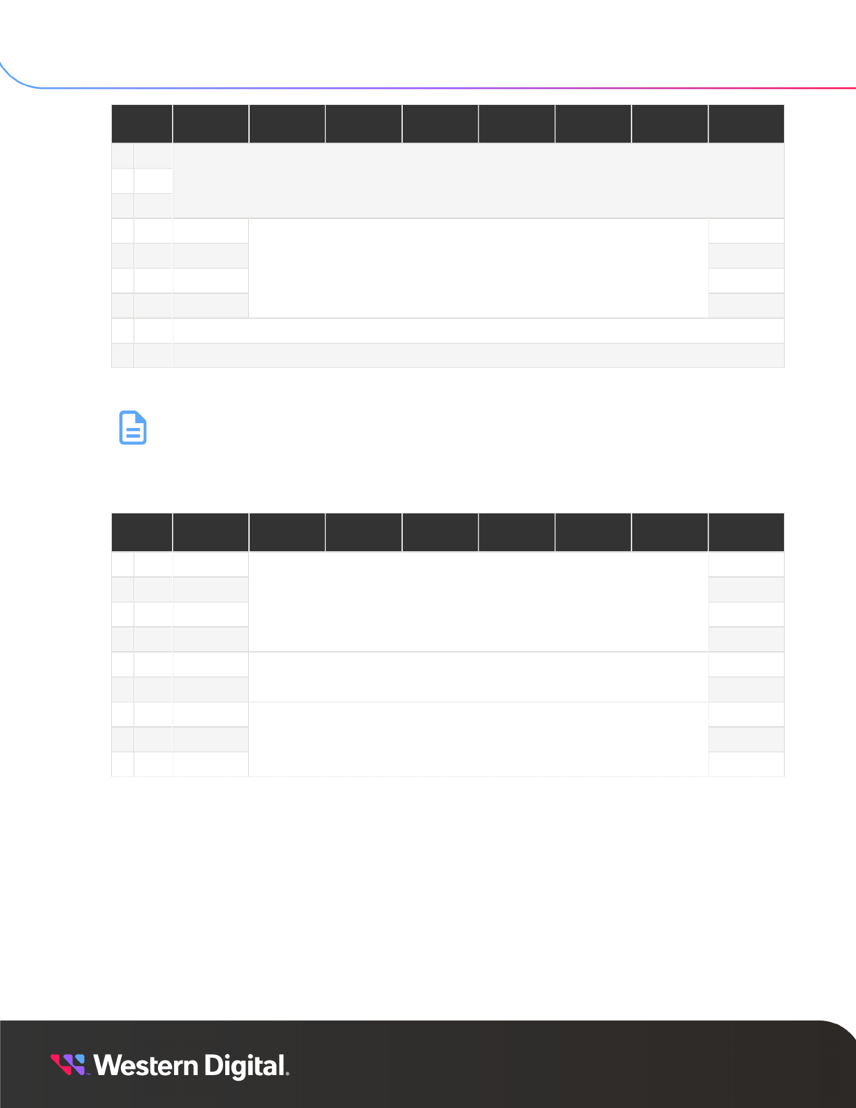
SES Reference
6. SCSI Commands
6.4 Inquiry
Byte/
Bit
7 6 5 4 3 2 1 0
3 03h
4 04h
5 05h
Reserved
6 06h (MSB)
7 07h
8 08h
9 09h
ALLOCATION LENGTH
(LSB)
10 0Ah Reserved
11 0Bh CONTROL (00h)
The REPORT LUNS command returns a list of logical unit identifiers supported by the SEP.
Note: Only LUN 0 is supported.
The following table displays the REPORT LUNS Data information:
Table 104: REPORT LUNS Data
Byte/
Bit
7 6 5 4 3 2 1 0
0 00h (MSB)
1 01h
2 02h
3 03h
LUN LIST LENGTH (00000008h)
(LSB)
4 04h (MSB)
7 07h
Reserved
(LSB)
8 08h (MSB)
... ...
15 0Fh
LUN (00000000h)
(LSB)
6.4.6
Mode Select (10)
The Mode Select command is used to customize optional operating modes in the SEP. By default, mode
parameters are saved in non-volatile memory; they remain in effect across SEP resets and power cycles
until changed by a host command.
The following are examples of Mode parameters which are supported by the SEP:
• Automatic spin-up: full power mode – all drives powered on and spun-up
The following table displays the MODE SELECT Command information:
95

SES Reference
6. SCSI Commands
6.4 Inquiry
Table 105: MODE SELECT Command
Byte/
Bit
7 6 5 4 3 2 1 0
0 00h OPERATION CODE (55h)
Reserved PF Reserved SP
3 03h
4 04h
5 05h
Reserved
(MSB)
(LSB)
CONTROL (00h)
6.4.7
Mode Sense (10)
The Mode Sense command is used to read the settings of optional operating modes in the SEP. The
specific operating parameters are selected by specifying a mode page, which contains the parameters.
The following table displays the MODE SENSE Command information:
Table 106: MODE SENSE Command
Byte/
Bit
7 6 5 4 3 2 1 0
0 00h OPERATION CODE (5Ah)
1 01h Reserved LLBAA DBD Reserved
2 02h PC PAGE CODE
3 03h SUBPAGE CODE
4 04h Reserved
5 05h
6 06h
Reserved
7 07h (MSB)
8 08h
ALLOCATION LENGTH
(LSB)
9 09h CONTROL (00h)
6.4.8
Log Select
The LOG SELECT command is used to erase the contents of non-volatile logs maintained by the SEP. The
PAGE CODE and SUBPAGE CODE argument are used to specify which log buffer is being operated on.
The following table displays the LOG SELECT Command information:
96

SES Reference
6. SCSI Commands
6.4 Inquiry
Table 107: LOG SELECT Command
Byte/
Bit
7 6 5 4 3 2 1 0
0 00h OPERATION CODE (4Ch)
1 01h Reserved PCR SP
2 02h PC PAGE CODEs
3 ... SUBPAGE CODE
4 04h
5 05h
6 06h
Reserved
7 07h (MSB)
8 08h
PARAMETER LIST LENGTH
(LSB)
9 09h CONTROL (00h)
6.4.9
Log Sense
The LOG SENSE command is used to read the contents of non-volatile logs maintained by the SEP. The
PAGE CODE and SUBPAGE CODE argument are used to specify which log buffer is being operated on.
The following table displays the LOG SENSE Command information:
Table 108: LOG SENSE Command
Byte/
Bit
7 6 5 4 3 2 1 0
0 00h OPERATION CODE (4Dh)
1 01h Reserved SP
2 02h PC PAGE CODE
3 03h SUBPAGE CODE
4 04h Reserved
5 05h (MSB)
6 06h
PARAMETER POINTER
(LSB)
7 07h (MSB)
8 08h
ALLOCATION LENGTH
(LSB)
9 09h CONTROL (00h)
97
