
Rockwell Automation Publication 1756-PM004L-EN-P - November 2023
Supersedes Publication 1756-PM004K-EN-P - November 2022
Programming Manual
Original Instructions
Logix 5000 Controllers I\O
and Tag Data
1756 ControlLogix, 1756 GuardLogix, 1769 CompactLogix,
1769 Compact GuardLogix, 1789 SoftLogix, 5069
CompactLogix, 5069 Compact GuardLogix, Studio 5000
Logix Emulate

Logix 5000 Controllers I/O and Tag Data
2 Rockwell Automation Publication 1756-PM004L-EN-P - November 2023
Important User Information
Read this document and the documents listed in the additional resources section about installation, configuration, and
operation of this equipment before you install, configure, operate, or maintain this product. Users are required to familiarize
themselves with installation and wiring instructions in addition to requirements of all applicable codes, laws, and standards.
Activities including installation, adjustments, putting into service, use, assembly, disassembly, and maintenance are required to
be carried out by suitably trained personnel in accordance with applicable code of practice.
I f this equipment is used in a manner not specified by the manufacturer, the protection provided by the equipment may be
impaired.
I n no event will Rockwell Automation, Inc. be responsible or liable for indirect or consequential damages resulting from the use
or application of this equipment.
The examples and diagrams in this manual are included solely for illustrative purposes. Because of the many variables and
requirements associated with any particular installation, Rockwell Automation, Inc. cannot assume responsibility or liability for
actual use based on the examples and diagrams.
No patent liability is assumed by Rockwell Automation, Inc. with respect to use of information, circuits, equipment, or software
described in this manual.
Reproduction of the contents of this manual, in whole or in part, without written permission of Rockwell Automation, I nc., is
prohibited.
Throughout this manual, when necessary, we use notes to make you aware of safety considerations.
WARNING: Identifies information about practices or circumstances that can cause an explosion in a hazardous environment, which may lead to personal injury
or death, property damage, or economic loss.
ATTENTION:
Identifies information about practices or circumstances that can lead to personal injury or death, property damage, or economic loss. Attentions
help you identify a hazard, avoid a hazard, and recognize the consequence.
IMPORTANT
Identifies information that is critical for successful application and understanding of the product.
Labels may also be on or inside the equipment to provide specific precautions.
SHOCK HAZARD: Labels may be on or inside the equipment, for example, a drive or motor, to alert people that dangerous voltage may be present.
BURN HAZARD: Labels may be on or inside the equipment, for example, a drive or motor, to alert people that surfaces may reach dangerous temperatures.
ARC FLASH HAZARD: Labels may be on or inside the equipment, for example, a motor control center, to alert people to potential Arc Flash. Arc Flash will cause
severe injury or death. Wear proper Personal Protective Equipment (PPE). Follow ALL Regulatory requirements for safe work practices and for Personal
Protective Equipment (PPE).
Rockwell Automation recognizes that some of the terms that are currently used in our industry and in this publication are not in
alignment with the movement toward inclusive language in technology. We are proactively collaborating with industry peers to
find alternatives to such terms and making changes to our products and content. Please excuse the use of such terms in our
content while we implement these changes.

Rockwell Automation Publication 1756-PM004L-EN-P - November 2023 3
Summary of changes
This manual includes new and updated information. Use these reference
tables to locate changed information.
Grammatical and editorial style changes are not included in this summary.
Global changes
None in this release.
New or enhanced features
Change
Topic
Added OPC UA Access information
Introduction - data access control on page 57
Added OPC UA Access information
Create a tag on page 31
Removed image Configure external access in the New Tag dialog
box on page 59
Removed image
Set up external access in the Tag Properties
dialog box on page 60
Removed image Set up a constant in the New Tag dialog box on
page 72
Removed image
Configure a constant in the Tag Properties dialog
box on page 72
New topic
OPC UA Access on page 67
New topic
Configure OPC UA Access on page 68
New topic
OPC UA options on page 68
New topic Set up OPC UA Access in the Tag Properties dialog
box on page 68
New topic
View and select OPC UA Access status on the Tag
Editor on page 69
New topic
OPC UA Access availability on page 69
New topic
Mapping tags to controllers for OPC UA Access on
page 70
New topic
Imported tag behavior for OPC UA Access on page
71

Rockwell Automation Publication 1756-PM004L-EN-P - November 2023 5
Table of Contents
Studio 5000 environment ........................................................................... 9
Additional resources .................................................................................. 10
Legal Notices .............................................................................................. 10
Chapter 1
I ntroduction ................................................................................................13
Requested packet interval ..........................................................................13
Communication format ............................................................................. 14
Direct or rack-optimized connection ................................................. 15
Ownership ............................................................................................ 15
E lectronic keying ........................................................................................ 17
More information ................................................................................ 18
Address I /O data ......................................................................................... 18
Buffer I/O .................................................................................................... 19
Chapter 2
I ntroduction ............................................................................................... 21
Tag type....................................................................................................... 22
Data type .....................................................................................................23
Tag scope .....................................................................................................25
Program parameter scope ........................................................................ 26
Guidelines for tags .....................................................................................27
Create a tag ................................................................................................. 31
Add extended properties to a tag ........................................................32
Create an array ........................................................................................... 33
Configure an array ............................................................................... 35
User-defined data types ............................................................................. 36
Guidelines for user-defined data types ..............................................38
Create a user-defined data type ..........................................................38
Add extended properties to a user-defined data type ....................... 39
Describe a user-defined data type ............................................................. 41
Activate pass-through and append descriptions .............................. 42
Paste a pass-through descripti on........................................................ 43
Address tag data .........................................................................................44
Alias tags .....................................................................................................44
Display alias infor mation ....................................................................46
Assign an alias ......................................................................................46
I ndirect addresses ...................................................................................... 47
Expressions.......................................................................................... 48
Array subscript out of range ............................................................... 48
Tag documentation ....................................................................................49
Summary of changes
Preface
Communicate with I/O modules
Organize tags

Table of Contents
6 Rockwell Automation Publication 1756-PM004L-EN-P - November 2023
Project documentation ........................................................................49
Chapter 3
I ntroduction ................................................................................................51
Precautions ..................................................................................................51
E nable forces ........................................................................................ 51
Disable or remove a force .................................................................... 51
Check force status ......................................................................................52
Force status indicator ..........................................................................52
GSV instruction .................................................................................... 53
W hen to use I /O force ................................................................................ 53
Force an input value ............................................................................. 54
Force an output value........................................................................... 54
Add an I /O force ......................................................................................... 54
Remove or disable forces ........................................................................... 55
Remove an individual force ................................................................. 55
Disable all I/O forces ............................................................................ 56
Remove all I /O forces ........................................................................... 56
Chapter 4
I ntroduction ............................................................................................... 57
E xternal access ........................................................................................... 57
Configure external access ..........................................................................58
E xternal access options .......................................................................58
Configure external access in the New Tag dialog box ....................... 59
Set up external access in the Tag Properties dialog box .................. 60
View and select external access status on the Tag E ditor ................ 60
Find a base tag with Go To................................................................... 61
External access availability ....................................................................... 62
User-defined type considerations ............................................................. 63
Add-on instructions external access considerations ...............................64
Tag mapping considerations .....................................................................66
I mported tag behavior ............................................................................... 67
OPC UA Access ............................................................................................ 67
Configure OPC UA Access ........................................................................ 68
OPC UA Access options ....................................................................... 68
Configure OPC UA Access in the Tag Properties dialog box ........... 68
View and select OPC UA Access status on the Tag Editor .................69
OPC UA Access availability ..................................................................69
Mapping tags to controller s for OPC UA Access ............................... 70
I mported tag behavior for OPC UA Access ........................................ 71
Constant value tags .................................................................................... 71
Force I/O
Data access control

Table of Contents
Rockwell Automation Publication 1756-PM004L-EN-P - November 2023 7
Configure constant tags ............................................................................ 71
Set up a constant in the New Tag dialog box .....................................72
Configure a constant in the Tag Properties dialog box.....................72
Designate a constant in the Tag Editor .............................................. 73
Track a constant tag ............................................................................. 74
Constant check box availability ................................................................. 74
Add-on instructions constant value considerations................................ 75
Index

Rockwell Automation Publication 1756-PM004L-EN-P - November 2023 9
Preface
This manual shows how to access I/O and tag data in Logix 5000 controllers.
This manual is one of a set of related manuals that show common procedures
for programming and operating Logix 5000 controllers.
For a complete list of common procedures manuals, refer to the Logix 5000
Controllers Common Procedures Programming Manual, publication
1756-PM001.
The term Logix 5000 controller refers to any controller based on the Logix
5000 operating system.
Rockwell Automation recognizes that some of the terms that are currently
used in our industry and in this publication are not in alignment with the
movement toward inclusive language in technology. We are proactively
collaborating with industry peers to find alternatives to such terms and
making changes to our products and content. Please excuse the use of such
terms in our content while we implement these changes.
The Studio 5000 Automation Engineering & Design Environment® combines
engineering and design elements into a common environment. The first
element is the Studio 5000 Logix Designer® application. The Logix Designer
application is the rebranding of RSLogix 5000® software and will continue to
be the product to program Logix 5000ő controllers for discrete, process,
batch, motion, safety, and drive-based solutions.
The Studio 5000® environment is the foundation for the future of
Rockwell Automation® engineering design tools and capabilities. The Studio
5000 environment is the one place for design engineers to develop all
elements of their control system.
Studio 5000 environment

Preface
10 Rockwell Automation Publication 1756-PM004L-EN-P - November 2023
Documents that contain additional information concerning related Rockwell
Automation products.
Resource
Description
Logix 5000 Controllers Program Parameters
Programming Manual, publication 1756-PM021
Describes how to use program parameters when
programming Logix 5000 controllers.
Product Certifications website,
http://ab.rockwellautomation.com
Provides declarations of conformity, certificates, and
other certification details.
View or download publications at
http://www.rockwellautomation.com/literature. To order paper copies of
technical documentation, contact the local Rockwell Automation distributor
or sales representative.
Rockwell Automation recognizes that some of the terms that are currently
used in our industry and in this publication are not in alignment with the
movement toward inclusive language in technology. We are proactively
collaborating with industry peers to find alternatives to such terms and
making changes to our products and content. Please excuse the use of such
terms in our content while we implement these changes.
Rockwell Automation publishes legal notices, such as privacy policies, license
agreements, trademark disclosures, and other terms and conditions on the
Legal Notices page of the R ockwell Automation website.
Software and Cloud Services Agreement
Review and accept the Rockwell Automation Software and Cloud Services
Agreement her e.
Open Source Licenses
The software included in this product contains copyrighted software that is
licensed under one or more open source licenses. Copies of those licenses are
included with the software. Corresponding Source code for open source
packages included in this product are located at their respective web site(s).
Alternately, obtain complete Corresponding Source code by contacting
Rockwell Automation via the Contact form on the Rockwell Automation
website:
http://www.rockwellautomation.com/global/about-us/contact/contact.page
Please include "Open Source" as part of the request text.
A full list of all open source software used in this product and their
corresponding licenses can be found in the OPE NSOURCE folder. The default
installed location of these licenses is
C:\Program Files (x86)\Common
Files\Rockwell\Help\<Product Name>\Release
Notes\OPENSOURCE\index.htm
.
Additional resources
Legal Notices

Preface
Rockwell Automation Publication 1756-PM004L-EN-P - November 2023 11

Rockwell Automation Publication 1756-PM004L-EN-P - November 2023 13
Chapter 1
Communicate with I/O modules
To communicate with an I /O module in your system, you add the module to
the I/O Configuration folder in the Controller Organizer.
When you add the module, you also define a specific configuration for the
module. While the configuration options vary from module to module, these
are some common options that you typically configure:
• Requested packet interval on page 13
• Communication format on page 14
• Electronic keying on page 17
The Logix 5000 controller uses connections to transmit I /O data.
Introduction
Requested packet interval

Chapter 1 Communicate with I/O modules
14 Rockwell Automation Publication 1756-PM004L-EN-P - November 2023
Term
Definition
Connection
A communication link between two devices, such as between a controller and an
I/O module, PanelView terminal, or another controller.
Connections are allocations of resources that provide more reliable
communications between devices than unconnected messages. The number of
connections that a single controller can have is limited.
You indirectly determine the number of connections the controller uses by
configuring the controller to communicate with other devices in the system. The
following types of communication use connections:
• I/O modules
• Produced and consumed tags
• Produced and consumed program parameters
• Certain types of Message (MSG) instructions (not all types use a connection)
Requested packet interval
(RPI)
The RPI specifies the period at which data updates over a connection. For example,
an input module sends data to a controller at the RPI that you assign to the module.
• Typically, you configure an RPI in milliseconds (ms). The range is 1 ms
(1000 microseconds)…536870.911 ms.
• If a ControlNet network connects the devices, the RPI reserves a slot in the
stream of data flowing across the ControlNet network. The timing of this slot may
not coincide with the exact value of the RPI, but the control system guarantees
that the data transfers at least as often as the RPI.
I n Logix 5000 controllers, I /O values update at a period that you configure in
the I /O configuration folder of the project. The values update asynchronous to
the execution of logic. At the specified interval, the controller updates a value
independently from the execution of logic.
WARNING:
Make sure that data memory contains the appropriate values throughout a task’s
execution. You can duplicate or buffer data at the beginning of the scan to provide reference values
for your logic.
• Programs within a task access input and output data directly from
controller-scoped memory.
• Logic within any task can change controller-scoped data.
• Data and I /O values are asynchronous and can change during the
course of a task’s execution.
• An input value referenced at the beginning of a task’s execution can be
different when referenced later.
• To prevent an input value from changing during a scan, copy the value
to another tag and use the data from there (buffer the values).
Tip: Starting with Logix Designer version 24, you can use program parameters to share data
between programs in much the same way as you have used controller-scoped tags. Input and
Output program parameters automatically buffer data, without using another program parameter
or tag. For more information on program parameters, refer to the Logix 5000 Controllers Program
Parameters Programming Manual, publication no. 1756-PM021.
See also
Logix 5000 Controllers Program Parameters Programming Manual,
publication no. publicati on no. 1756-PM021
The communication format that you choose determines the data structure for
the tags that are associated with the module. Many I/O modules support
Communication format

Chapter 1 Communicate with I/O modules
Rockwell Automation Publication 1756-PM004L-EN-P - November 2023 15
different formats. Each format uses a different data structure. The
communication format that you choose also determines:
• Direct or rack-optimized connection on page 15.
• Ownership on page 15.
The Logix 5000 controller uses connections to transmit I/O data. These
connections can be direct connections or rack-optimized connections.
Term
Definition
Direct connection
A direct connection is a real-time, data transfer link between the controller and an I/O module. The controller
maintains and monitors the connection with the I/O module. Any break in the connection, such as a module fault or
the removal of a module while under power, sets fault bits in the data area associated with the module.
A direct connection is any connection that does not use the Rack Optimization Comm Format.
Rack-optimized connection
For digital I/O modules, you can select rack-optimized communication. A rack-optimized connection consolidates
connection usage between the controller and all the digital I/O modules in the chassis (or DIN rail). Rather than
having individual, direct connections for each I/O module, there is one connection for the entire chassis (or DIN rail).
In a Logix 5000 system, modules multicast data. This means that multiple
devices can receive the same data at the same time from a single device.
W hen you choose a communication format, you have to choose whether to
establish an owner or listen-only relationship with the module.
Direct or rack-optimized
connection
Ownership

Chapter 1 Communicate with I/O modules
16 Rockwell Automation Publication 1756-PM004L-EN-P - November 2023
Term
Definition
Owner controller
The controller that creates the primary configuration and communication connection to a module. The owner
controller writes configuration data and can establish a connection to the module.
An owner connection is any connection that does not include Listen-Only in its Comm Format.
Listen-only connection
An I/O connection where another controller owns/provides the configuration data for the I/O module. A controller
using a listen-only connection only monitors the module. It does not write configuration data and can only maintain
a connection to the I/O module when the owner controller is actively controlling the I/O module.
Use the following table to choose the type of ownership for a module.
If module is
And another controller
And you want to
Then use this type of connection
Input module
Does not own the module
------------------------------------>
Owner (not listen-only)
Owns the module
Maintain communication with the module if it loses
communication with the other controller
Owner (not listen-only)
Use the same configuration as the other owner
controller.
Stop communication with the module if it loses
communication with the other controller
Listen-only
Output module Does not own the module ------------------------------------> Owner (such as, not listen-only)
Owns the module
------------------------------------>
Listen-only
There is a noted difference in controlling input modules versus controlling
output modules. The following table lists the differences.
Controlling
This Ownership
Description
Input modules Owner An input module is configured by a controller that establishes a connection as an owner. This configuring
controller is the first controller to establish an owner connection.
Once an input module has been configured (and owned by a controller), other controllers can establish owner
connections to that module. This lets additional owners to continue to receive multicast data if the original
owner controller breaks its connection to the module. All other additional owners must have the identical
configuration data and identical communications format that the original owner controller has; otherwise, the
connection attempt is rejected.

Chapter 1 Communicate with I/O modules
Rockwell Automation Publication 1756-PM004L-EN-P - November 2023 17
Controlling
This Ownership
Description
Listen-only
Once an input module has been configured (and owned by a controller), other controllers can establish a
listen-only connection to that module. These controllers can receive multicast data while another controller
owns the module. If all owner controllers break their connections to the input module, all controllers with
listen-only connections no longer receive multicast data.
Output modules
Owner
An output module is configured by a controller that establishes a connection as an owner. Only one-owner
connection is allowed for an output module. If another controller attempts to establish an owner connection, the
connection attempt is rejected.
Listen-only
Once an output module has been configured (and owned by one controller), other controllers can establish
listen-only connections to that module. These controllers can receive multicast data while another controller
owns the module. If the owner controller breaks its connection to the output module, all controllers with
listen-only connections no longer receive multicast data.
Electronic Keying reduces the possibility of using the wrong device in a
control system. E lectronic Keying compares the device defined in the project
to the installed device. I f keying fails, a fault occurs.
These attributes are compared:
Attribute
Description
Vendor
The device manufacturer.
Device Type
The general type of the device, for example, digital I/O module.
Product Code The specific type of device. The
Product Code
maps to a catalog number.
Major Revision
A number that represents the functional capabilities of a device.
Minor Revision
A number that represents behavior changes in the device.
These Electronic Keying options are available:
Keying Option
Description
Compatible Module
Lets the installed device accept the key of the device that is defined in the
project when the installed device can emulate the defined device. Typically,
use
Compatible Module
to replace a device with another device that has these
characteristics:
• Same catalog number
• Same or higher Major Revision
• Minor Revision:
• If the Major Revision is the same, the Minor Revision must be the same or
higher.
• If the Major Revision is higher, the Minor Revision can be any number.
Disable Keying
Indicates that the keying attributes are not considered when attempting to
communicate with a device. With
Disable Keying
, communication can occur
with a device other than the type specified in the project.
ATTENTION:
Be extremely cautious when using
Disable Keying.
If used
incorrectly, this option can lead to personal injury or death, property damage,
or economic loss.
We strongly recommend not using
Disable Keying
.
If using
Disable Keying
, take full responsibility for understanding whether the
device being used can fulfill the functional requirements of the application.
Exact Match
Indicates that all keying attributes must match to establish communication. If
any attribute does not match precisely, communication with the device does
not occur.
Carefully consider the implications of each keying option when selecting one.
Electronic keying

Chapter 1 Communicate with I/O modules
18 Rockwell Automation Publication 1756-PM004L-EN-P - November 2023
IMPORTANT
Changing Electronic Keying parameters online interrupts connections to the device and any
devices that are connected through the device. Connections from other controllers can also
be broken.
A loss of data may occur if an I/O connection to a device is interrupted.
For more information on Electronic Keying, see Electronic Keying in <LOGI
X5K> Control Systems Application Technique, publication LOGIX-AT001.
I/O information is presented as a set of tags.
• Each tag uses a structure of data. The structure depends on the specific
features of the I /O module.
• The name of the tag is based on the location of the I/O module in the
system.
• W hen you add a module to the I /O Configuration folder, the software
automatically creates controller-scoped tags for the module in
Controller Tags.
An I/O address uses this format:
Where
Is
Location Network location
LOCAL = same chassis or DIN rail as the controller
More information
Address I/O data

Chapter 1 Communicate with I/O modules
Rockwell Automation Publication 1756-PM004L-EN-P - November 2023 19
Where
Is
ADAPTER_NAME = identifies remote communication adapter or bridge module
Slot
Slot number of I/O module in its chassis or DIN rail
Type Type of data
I = input
O = output
C = configuration
S = status
Member
Specific data from the I/O module; depends on what type of data the module can store.
• For a digital module, a Data member usually stores the input or output bit values.
• For an analog module, a Channel member (CH#) usually stores the data for a channel.
SubMember
Specific data related to a Member.
Bit
Specific point on a digital I/O module; depends on the size of the I/O module (0–31 for a 32-point
module)
Buffering is a technique in which logic does not directly reference or
manipulate the tags of real I /O devices. I nstead, the logic uses a copy of the
I/O data. Buffer I/O in the following situations:
• To prevent an input or output value from changing during the
execution of a program. (I /O updates asynchronous to the execution of
logic.)
• To copy an input or output tag to a member of a structure or element
of an array.
Tip: Starting with Logix Designer version 24, you can use program parameters to buffer data in a
program without having to copy the data to a second tag. Input and Output program parameters
automatically buffer data while the program routines execute. For more information on program
parameters, refer to the Logix 5000 Controllers Program Parameters Programming Manual,
publication no. 1756-PM021.
Follow these steps to buffer I /O.
1. On the rung before the logic for the function, copy or move the data
from the required input tags to their corresponding buffer tags.
2. I n the logic of the function, reference the buffer tags.
3. On the rung after the function, copy the data from the buffer tags to
the corresponding output tags.
The example copies inputs and outputs to the tags of a structure for a drill
machine. The examples are of buffer I /O by mapping values to tags.
The main routine of the program executes the subroutines in this sequence.
Buffer I/O

Chapter 1 Communicate with I/O modules
20 Rockwell Automation Publication 1756-PM004L-EN-P - November 2023
The map_inputs routine copies the values of input devices to their
corresponding tags that are used in the drill routine.
The drill routine executes the logic for the drill machine.
The map_outputs routine copies the values of output tags in the drill routine
to their corresponding output devices.
The example uses the CPS instruction to copy an array of data that represent
the input devices of a DeviceNet network.
EXAMPLE
Buffer I/O using CPS instruction
Local:0:I.Data stores the input data for the DeviceNet network that is connected to the 1756-DNB module in slot 0. To
synchronize the inputs with the application, the CPS instruction copies the input data to input_buffer.
• While the CPS instruction copies the data, no I/O updates can change the data.
As the application executes, it uses the input data in input_buffer for its inputs.
See also
Logix 5000 Controllers Program Parameters Programming Manual,
publication no. 1756-PM021

Rockwell Automation Publication 1756-PM004L-EN-P - November 2023 21
Chapter 2
Organize tags
With a Logix 5000 controller, you use a tag (alphanumeric name) to address
data (variables).
Term
Definition
Tag
A text-based name for an area of the controller’s memory where data is stored.
• Tags are the basic mechanism for allocating memory, referencing data from logic, and monitoring
data.
• The minimum memory allocation for a tag is four bytes.
• When you create a tag that stores data that requires less than four bytes, the controller allocates four
bytes, but the data only fills the part it needs.
The controller uses the tag name internally and does not need to
cross-reference a physical address.
• In conventional programmable controllers, a physical address
identifies each item of data.
• Addresses follow a fixed, numeric format that depends on the type
of data, such as N7:8, F8:3.
• Symbols are required to make logic easier to interpret.
• I n Logix 5000 controllers, there is no fixed, numeric format. The tag
name itself identifies the data. This lets you:
• Organize your data to mirror your machinery.
• Document (through tag names) your application as you develop it.
Introduction

Chapter 2 Organize tags
22 Rockwell Automation Publication 1756-PM004L-EN-P - November 2023
Example
Item
Description
Analog I/O Device
Integer Value
Storage Bit
Counter
Timer
Digital I/O Device
The tag type defines how the tag operates within your project.
If you want the tag to
Then select this type
Store a value or values for use by logic within the project
Base
Represent another tag Alias
Send data to another controller
Produced
Receive data from another controller Consumed
I f you plan to use produced or consumed tags, you must follow additional
guidelines as you organize your tags.
See also
Logix 5000 Controllers Produced and Consumed Tags Programming
Manual, publication no. 1756-PM011
Tag type

Chapter 2 Organize tags
Rockwell Automation Publication 1756-PM004L-EN-P - November 2023 23
Data type applies to tags and structures.
Term
Definition
Data type
The data type defines the type of data that a tag stores, such as a bit, integer, floating-point value,
string, and so forth.
Structure
A data type that is a combination of other data types.
• A structure is formatted to create a unique data type that matches a specific need.
• Within a structure, each individual data type is called a member.
• Like tags, members have a name and data type.
• A Logix 5000 controller contains a set of predefined structures (data types) for use with
specific instructions such as timers, counters, Function Blocks, and so forth.
• You can create your own structures, called a user-defined data type
This table outlines the most common data types and when to use each.
For
Select
Analog device in floating-point mode REAL
Analog device in integer mode (for very fast sample rates)
INT
ASCII characters
String
Bit
BOOL
Counter
COUNTER
Digital I/O point
BOOL
Floating-point number
REAL
Integer (whole number)
DINT
Sequencer
CONTROL
Timer
TIMER
To add Extended Properties
You have the option to add extended properties to select tags. The extended
properties include:
• Min
• Max
• Engineering Units
• State0
• State1
When these properties are added, their values are made available for use by
some R ockwell Automation H MI s.
Extended properties for a tag are added and modified in the Tag Properties
pane.
The minimum memory allocation for a tag is four bytes. When you create a
tag that stores data that requires less than four bytes, the controller allocates
four bytes, but the data only fills the part it needs.
Data Type
Bits
31
16
15
8
7
1
0
BOOL
Not used
0 or 1
Data type

Chapter 2 Organize tags
24 Rockwell Automation Publication 1756-PM004L-EN-P - November 2023
SINT
Not used
-128…+127
INT
Not used
-32,768…+32,767
DINT
-2,147,483,648…+2,147,483,647
REAL
-3.40282347E
38
…-1.17549435E
-38
(negative values)
0
-1.17549435E
-38
-…3.40282347E
38
(positive values)
The COUNTER and TI ME R data types are examples of commonly used
structures.
Item
Description
To expand a structure and display its members, click the icon.
To collapse a structure and hide its members, click the icon.
Members of running_seconds.
COUNTER Structure.
TIMER Structure.
Data Type Members.
To copy data to a structure, use the COP instruction.
See also
Logix 5000 Controllers General Instructions Reference Manual,
publication no. 1756-RM003

Chapter 2 Organize tags
Rockwell Automation Publication 1756-PM004L-EN-P - November 2023 25
When you create a tag, you define it as either a controller tag (global data) or a
local tag for a specific program (local data).
A Logix 5000 controller lets you divide your application into multiple
programs, each with its own data. There is no need to manage conflicting
local tag names between programs. This makes it easier to reuse both code
and tag names in multiple programs.
Data at the program scope is isolated from other programs.
• Routines cannot access data that is at the local scope (local tag) of
another program.
• You can reuse the tag name of a local tag in multiple programs.
• For example, both Program_A and Program_B can have a local tag
named Tag_4.
• You can also use program parameters to share data between
programs as an alternative to controller-scope tags. See Program
parameter scope.
Avoid using the same name for both a controller tag and a local tag. Within a
program, you cannot reference a controller tag if a local tag of the same name
exists for that program.
Certain tags must be controller scope (controller tags).
Tag scope

Chapter 2 Organize tags
26 Rockwell Automation Publication 1756-PM004L-EN-P - November 2023
If you want to use the tag
Then assign this scope
In more than one program in the project
Controller scope (controller tags)
In a Message (MSG) instruction
To produce or consume data
In any of the seven AXIS data types
To communicate with a PanelView terminal
None of the above
Program scope (local tags)
See also
Program parameter scope on page 26
Program parameters are similar to tags:
• You create program parameters at the program level, and use them to
manage data.
• Program parameters behave like controller-scope tags in that they can
pass data between programs.
Among other benefits, program parameters allow you to clearly define the
inputs to the routines in a program, and the outputs from those routines.
Input and Output parameters also automatically buffer data, so that you do
not have to create separate tags to buffer I O data.
I f you want to restrict data to only the local program scope, you can use local
tags. See Tag scope .
For more information on program parameters, refer to the Logix 5000
Controllers Program Parameters Programming Manual, publication no.
1756-PM021.
See also
Tag scope on page 24
Program parameter scope


Chapter 2 Organize tags
28 Rockwell Automation Publication 1756-PM004L-EN-P - November 2023
Guideline
Details
Create user-defined data types
User-defined data types (structures) let you organize data to match your machine or process. A
user-defined data type provides these advantages:
• One tag contains all the data related to a specific aspect of your system. This keeps related data
together and easy to locate, regardless of its data type.
• Each individual piece of data (member) gets a descriptive name. This automatically creates an
initial level of documentation for your logic.
• You can use the data type to create multiple tags with the same data layout.
For example, use a user-defined data type to store all the parameters for a tank, including
temperatures, pressures, valve positions, and preset values. Then create a tag for each of your tanks
based on that data type.
Use arrays to quickly create a group
of similar tags
An array creates multiple instances of a data type under a common tag name.
• Arrays let you organize a block of tags that use the same data type and perform a similar function.
• You organize the data in one, two, or three dimensions to match what the data represents.
For example, use a two-dimensional array to organize the data for a tank farm. Each element of the
array represents a single tank. The location of the element within the array represents the
geographic location of the tank.
Important:
Minimize the use of BOOL arrays. Many array instructions do not operate on BOOL arrays.
This makes it more difficult to initialize and clear an array of BOOL data.
• Typically, use a BOOL array for the bit-level objects of a PanelView screen.
• Otherwise, use the individual bits of a DINT tag or an array of DINTs.
Take advantage of program-scoped tags
If you want multiple tags with the same name, define each tag at the program scope (local tags) for a
different program. This lets you reuse both logic and tag names in multiple programs.
Avoid using the same name for both a controller tag and a local tag. Within a program, you cannot
reference a controller tag if a tag of the same name exists as a local tag for that program.
Certain tags must be controller scope (controller tag).
If you want the tag
Then assign this scope
In more than one program in the project Controller scope (controller tags)
In a Message (MSG) instruction
To produce or consume data
In any of the seven AXIS data types
To communicate with a PanelView terminal
None of the above
Program scope (local tags)
For integers, use the DINT data type To increase the efficiency of your logic, minimize the use of SINT or INT data types. Whenever
possible, use the DINT data type for integers.
• A Logix5000 controller typically compares or manipulates values as 32-bit values (DINTs or
REALs).
• The controller typically converts a SINT or INT value to a DINT or REAL value before it uses the
value.
• If the destination is a SINT or INT tag, the controller typically converts the value back to a SINT or
INT value.
• The conversion to or from SINTs or INTs occurs automatically with no extra programming. But it
takes extra execution time and memory.
Use most restrictive external access
External access limits the exposure of controller tags by defining a user’s ability to edit tags to
Read/Write, Read Only and None. This helps:
• Reduce the risk of inadvertently changing tags.
• Reduce the number of tags to browse when configuring HMI.
See External access.
Enable constant attribute for tags that should not be
changed by logic
You can assign a constant value to a tag to prevent the table-backed data from being changed
programmatically. This helps reduce the risk of inadvertently changing tags.
See Constant value tags.

Chapter 2 Organize tags
Rockwell Automation Publication 1756-PM004L-EN-P - November 2023 29
Guideline
Details
Limit a tag name to 40 characters
Here are the rules for a tag name:
• Only alphabetic characters (A–Z or a–z), numeric characters (0–9),
and underscores (_)
• Must start with an alphabetic character or an underscore
• No more than 40 characters
• No consecutive or trailing underscore characters (_)
• Not case sensitive
Use mixed case
Although tags are not case sensitive (upper case A is the same as lower case a), mixed case is easier
to read.
These tags are easier to read
Than these tags
Tank_1
TANK_1
Tank1 TANK1
tank_1
tank1
Consider the alphabetical order of tags
Logix Designer application displays tags of the same scope in alphabetical order. To make it easier to
monitor related tags, use similar starting characters for tags that you want to keep together.
Starting each tag for a tank with ‘Tank’ keeps the tags
together.
Otherwise, the tags may end up
separated from each other.
Using extended properties in logic
You can access limit extended properties defined on tags using the .@Min and .@Max syntax.
However, you cannot write to extended properties values in logic.
For example, in the Ladder Editor, you can use limit extended properties on an instruction’s source
operand.

Chapter 2 Organize tags
30 Rockwell Automation Publication 1756-PM004L-EN-P - November 2023
Guideline
Details
Using extended properties in logic (continued)
In the Function Block Editor, you can access extended properties in logic by wiring an Input
Reference to a block’s input pins.
In the Structured Text Editor, you can access limit extended properties in logic on the right hand side
of an assignment operation or in a comparison statement. You can also access limit extended
properties in logic when you embed structured text in the Sequential Function Chart Editor.
You need to know which tags have limit extended properties associated with them as there is no
indication in the Tag Browser that extended properties are defined for a tag. However, if you try to
use extended properties that have not been defined for a tag, the editors show a visual indication
(that is: a rung error in Ladder Logic, a verification error X in Function Block Diagrams, and the error
underlined in Structured Text) and the routine does not verify.
• The following restrictions apply when you use extended properties in logic.
• You must use extended properties as an input operand.
You can use extended properties on an instruction as long as the input (source) operand is a
non-boolean atomic data type. That is, if an instruction has operands whose data type is
non-atomic or BOOL, limit extended properties cannot be used. For example, the ALMD
instruction in Ladder Logic does not support extended properties because its configurable
operands are of type BOOL.
In the Ladder Editor, when limit extended properties is used in logic, the value field associated
with the source operand is unavailable. You can change the tag's extended properties only in
the Tag Editor
Properties
Pane.
• You cannot access alias tags with extended properties in logic.
If you use alias tag extended properties in logic, the routine does not verify.

Chapter 2 Organize tags
Rockwell Automation Publication 1756-PM004L-EN-P - November 2023 31
Guideline
Details
Using extended properties in logic (continued)
•
Array Tags are constrained
A constraint on array tags applies if the array tag uses indirect addressing to access limit
extended properties. If an array tag is using indirect addressing to access limit extended
properties in logic, the following conditions apply.
• If the Array Tag has limit extended properties configured, the extended properties are applied
to any array element that does not explicitly have that particular extended property configured.
For example, if the MyArray has
Max
configured to 100, then any element of the array that does
not have
Max
configured inherits the value of 100 when being used in logic. However, it is not
visible to you that the value inherited from MyArray is configured in the tag properties.
• At least one array element must have specific limit extended property configured for indirectly
referenced array logic to verify. For example, if MyArray[x].@Max is being used in logic, at least
one array element of MyArray[] must have
Max
extended property configured if
Max
is not
configured by MyArray. If this is not done, if you attempt to access
Max
in logic on MyArray in
logic, the routine does not verify.
• Under the following circumstances the software uses a data type default value:
• Array is accessed programmatically with indirect reference.
• Array tag does not have the extended property configured.
• Member of array does not have the extended property configured. For example for Array of
SINT type, when max limit is called in logic for a member, the value 127 is used.
• Removing Extended Properties
You cannot remove extended properties that are accessed in logic when the project is online with
the controller. The
Max
and
Min
check boxes in the
Extended Properties
box in the Tag
Properties
pane are unavailable. You have to go offline to remove the extended properties.
Removing extended properties in logic on structure tags is unavailable at the tag level. For
example, if MyUDTTag has 2 members, Mem1 being a DINT and the Mem2 being a SINT, if you define
limit extended properties in Logic on both members, but are only accessing
Max
extended
properties on Mem1, the
Max
check box is unavailable in
Extended Properties
for both members.
You are not able to remove the
Max
extended properties for MyUDTTag .Mem2 online.
The same applies for Array tags. If you define limit extended properties on an array element and
that element is accessed in logic, then you cannot remove the limit extended properties from any
of the array elements.
See also
External access on page 57
Constant value tags on page 71
Use the Tag Editor to create and edit tags using a spreadsheet-style view of
the tags.
IMPORTANT
The Logix Designer application also automatically creates tags when you:
• Add an element to a sequential function chart (SFC).
• Add a function block instruction to a function block diagram.
To create a tag
1. In the Controller Organizer, right-click Controller Tags and then
select Edit Tags.
2. In the Tag Editor, from the Scope box, choose a scope for the tag using
the table as a guide.
If You Use The Tag
Then Choose
In more than one program within the project
The controller name
Create a tag

Chapter 2 Organize tags
32 Rockwell Automation Publication 1756-PM004L-EN-P - November 2023
If You Use The Tag
Then Choose
As a producer or consumer
In any of the seven AXIS data types
In a message
In only one program within the project
Program that uses the tag
This also limits the tag display to only tags with the same scope.
3. In the Name box, type a name for the tag.
4. In the Data Type box, enter the data type.
You can also select the Browse button and then in the Select Data Type
dialog box, choose a data type for the tag.
5. (optional) In the Description box, type a description for the tag.
6. (optional) Select the Constant check box if you want the tag to have a
constant value.
7. In the External Access box, choose the external access for the tag.
See Data access control for information on the External Access and
Constant attributes.
8. In OPC UA Access, set the access that external OPC UA clients have to
tags.
See also
Data access control on page 57
To add extended properties to a tag:
1. I n the Tag Editor, select the tag.
2. I f the Properties pane is not visible, select Properties.
3. In the Properties pane, select Extended Properties, and select the
properties that you want to add.
Add extended properties to
a tag

Chapter 2 Organize tags
Rockwell Automation Publication 1756-PM004L-EN-P - November 2023 33
The entries in the list depend on the tag’s data type. You can select
more than one property.
For data type
You can add the following extended property
Array and string
Engineering Unit
BOOL State0
State1
Engineering Unit
DINT, INT, LINT, SINT, and REAL and corresponding array
member
Min
Max
Engineering Unit
The added properties are displayed in the Tag Editor Properties pane
under Data.
Clear the check box to remove the property from the tag. This also
removes the properties from the Data properties category. Note that
once the property is removed, any value associated to the property is
removed from the system.
The list is not available for other types of tags. The following table lists
the minimum and maximum values for DI NT, I NT, LI NT, SINT, and
REAL Data Types.
Data Type
Range
DINT -2,147,483,648...2,147,483,647
INT
-32,768...32,767
LINT
0...32535129599999999
SINT
-128...127
REAL -3.402823E38 to -1.1754944E-38 (negative values)
and
0
and
1.1754944E-38 to 3.402823E38 (positive values)
Arrays can also be used to organize data.
Term
Definition
Array A tag that contains a block of multiple pieces of data.
Create an array

Chapter 2 Organize tags
34 Rockwell Automation Publication 1756-PM004L-EN-P - November 2023
Term
Definition
•
An array is similar to a file.
• Within an array, each individual piece of data is called an element.
• Each element uses the same data type.
• An array tag occupies a contiguous block of memory in the controller, each element in
sequence.
• You can use array and sequencer instructions to manipulate or index through the elements of
an array.
• You organize the data into a block of one, two, or three dimensions.
The subscript identifies each individual element within the array. A subscript
starts at 0 and extends to the number of elements minus 1 (zero based).
Item
Description
To expand a structure and display its members, click the icon.
To collapse a structure and hide its members, click the icon.
Six elements of timer_presets.
This two-dimensional array contains nine elements (three by three array).
This one-dimensional array contains six elements of the DINT data type. In this example, a single timer
instruction times the duration of several steps. Each step requires a different preset value. Because all
the values are the same data type (DINTs), use an array.
This example compares a structure to an array.
This is a tag that uses the Timer structure (data type).
This is a tag that uses an array of the Timer data type.

Chapter 2 Organize tags
Rockwell Automation Publication 1756-PM004L-EN-P - November 2023 35
EXAMPLE
Two-dimension array
A drill machine can drill one through five holes in a book. The machine requires a value for the
position of each hole from the leading edge of the book. To organize the values into
configurations, use a two-dimension array. The first subscript indicates the hole that the value
corresponds and the second subscript indicates how many holes are to be drilled (one through
five).
In the Tag Editor, the elements are in the order in the graphic.
Item
Description
The rightmost dimension increments to its maximum value then starts over.
When the rightmost dimension starts over, the dimension to the left increments by one.
This array contains a two-dimensional grid of elements, six elements by six elements.
To create an array, you create a tag and assign dimensions to the data type.
Configure an array

Chapter 2 Organize tags
36 Rockwell Automation Publication 1756-PM004L-EN-P - November 2023
1. In the Controller Organizer, right-click Controller Tags and then
select Edit Tags.
2. In the Tag Editor, from the Scope box, choose a scope for the tag using
the table as a guide.
If You Use The Tag
Then Choose
In more than one program within the project
The controller name
As a producer or consumer
In any of the seven AXIS data types
In a message
In only one program within the project
Program that uses the tag
This also limits the tag display to only tags with the same scope.
3. In the Name box, type a name for the tag.
4. In the Data Type box, enter the data type the array dimensions. I n the
table, Data_type represents the actual data type you enter.
If the tag is
Then type
Where
One-dimension array Data_type[x] Data_type is the type of data that the tag stores.
• X is the number of elements in the first
dimension.
• Y is the number of elements in the second
dimension.
• Z is the number of elements in the third
dimension.
Two-dimension array
Data_type[x,y]
Three-dimension array
Data_type[x,y,z]
You can also select the Browse button and then in the Select Data Type
dialog, choose a data type and the array dimensions for the array.
User-defined data types (structures) let you organize your data to match your
machine or process.
EXAMPLE
User-defined data type that stores a recipe.
In a system of several tanks, each tank can run a variety of recipes. Because the recipe requires
a mix of data types (REAL, DINT, BOOL, so forth), a user-defined data type is used.
User-defined data types

Chapter 2 Organize tags
Rockwell Automation Publication 1756-PM004L-EN-P - November 2023 37
An array that is based on this data type looks like this example.
Item
Description
Array of recipes
First recipe
Members of the recipe
Array containing three elements of the TANK data type
EXAMPLE
User-defined data type that stores the data that is required to run a machine.
Because several drill stations require the following mix of data, use a user-defined data type.
An array that is based on this data type would look like this example.
Item
Description
Array of drills

Chapter 2 Organize tags
38 Rockwell Automation Publication 1756-PM004L-EN-P - November 2023
First drill
Data for the drill
Array containing four elements of the DRILL_STATION data type
When you create a user-defined data type, use these guidelines.
• If you include members that represent I /O devices, you must use logic
to copy the data between the members in the structure and the
corresponding I /O tags. R efer to Address I/O data.
• If you include an array as a member, limit the array to a single
dimension. Multi-dimension arrays are not permitted in a
user-defined data type.
• When you use the BOOL, SI NT, or I NT data types, place members that
use the same data type in sequence.
More Efficient
Less Efficient
BOOL
BOOL
BOOL
DINT
BOOL
BOOL
DINT
DINT
DINT
BOOL
See also
Address I/O data on page 18
Use this procedure to create user-defined data types.
To create a user-defined data type
1. In the Controller Organizer, expand Data Types, then right-click
User-Defined and then select New Data Type.
2. In the Data Type Editor, in Name, type a name for the user-defined
data type.
3. (optional) I n Description, type a description for the user-defined data
type.
Guidelines for user-defined
data types
Create a user-defined data
type

Chapter 2 Organize tags
Rockwell Automation Publication 1756-PM004L-EN-P - November 2023 39
4. Select Add Member to add a new data type member.
5. In Name, type a name for the data type member.
6. In Data Type, enter the data type for the member.
Or, select the Browse button and in the Select Data Type dialog box,
choose a data type for the tag.
Limit any arrays to a single dimension. See Configure an array.
7. (optional) I n Description, type a description for the data type member.
8. I f the Properties pane is not visible, select Properties to display the
properties for the data type member.
Tip: You may have to click in the data type member again to display the properties for the member
instead of the properties for the data type.
a. In the Properties pane, select the box next to External Access, and
select an attribute.
b. To display the value of the member in a different style (radix), select
the box next to Style, and select the style.
9. Select Apply.
10 . Repeat this procedure to add as many members as needed.
See also
Configure an array on page 35
Add Min, Max, Engineering Units, State 0, and State 1 properties to a data
type or its member. When you add these properties, other Rockwell
Automation H MI s can use their values.
Add extended properties to
a user-defined data type

Chapter 2 Organize tags
40 Rockwell Automation Publication 1756-PM004L-EN-P - November 2023
To add extended properties to a user-defined data type
1. In the Controller Organizer, expand Data Types, then expand
User-Defined. Right-click the user-defined data type and select
Properties.
2. In the Data Type Editor, either:
• Select the data type Name to choose the data type.
• Select the data type member Name to choose the data type member.
3. I f the Properties pane is not visible, select Properties.
4. Select Extended Properties.
5. Select one or more properties to add. The properties in the list depend
on the selected data type or member’s data type.
For data type
Add these extended property
Array and string
Engineering Unit
BOOL
State 0
State 1
Engineering Unit
DINT, INT, LINT, SINT, and REAL
Min
Max
Engineering Units
IMPORTANT
The list is unavailable for other types of data type members.

Chapter 2 Organize tags
Rockwell Automation Publication 1756-PM004L-EN-P - November 2023 41
The table shows the minimum and maximum values for DINT, INT, LINT,
SI NT, and REAL Data Types.
Data Type
Range
DINT
-2,147,483,648…2,147,483,647
INT
-32,768…32,767
LINT
0…32535129599999999
SINT
-128…127
REAL -3.402823E38…-1.1754944E-38 (negative values)
and
0
and
1.1754944E-38…3.402823E38 (positive values)
I n version 13 or later, the Logix Designer application lets you automatically
build descriptions out of the descriptions in your user-defined data types.
This greatly reduces the amount of time you have to spend documenting your
project.
As you organize your user-defined data types, keep in mind these features of
the Logix Designer application.
Item
Description
Describe a user-defined
data type

Chapter 2 Organize tags
42 Rockwell Automation Publication 1756-PM004L-EN-P - November 2023
Pass through of descriptions
—When possible, the Logix Designer application looks for an available
description for a tag, element, or member.
• Descriptions in user-defined data types ripple through to the tags that use that data type.
• Description of an array tag ripples through to the elements and members of the array.
Append description to base tag—the Logix Designer application automatically builds a description for
each member of a tag that uses a user-defined data type. It starts with the description of the tag and
then adds the description of the member from the data type.
Paste pass-through description
—Use the data type and array description as a basis for more specific
descriptions.
In this example, Tank became West Tank.
The Logix Designer application uses different colors for descriptions.
If the Color of the Description Is
It is a
Gray
Pass-through description
Black
Manually entered description
Follow these steps to use pass-through descriptions and append to base tag
descriptions.
To activate pass-through and append descriptions
1. In the Controller Organizer, right-click the controller at the top and
then select Properties.
2. In the Controller Properties dialog box, select the Project tab.
Activate pass-through and
append descriptions

Chapter 2 Organize tags
Rockwell Automation Publication 1756-PM004L-EN-P - November 2023 43
3. Check Show Pass-Through Descriptions and Append to Base Tag
Descriptions.
4. Select OK.
Choose this command to paste a pass-through value of an item into the
Description, Engineering Unit, State 0, or State 1 field of another item.
Follow these steps to use a pass-through description as the starting point for a
more specific description.
1. In the Controller Tags Editor, right-click the Description box, and
then select Paste Pass-Through.
2. Edit the description and press CTRL+Enter.
Paste a pass-through
description

Chapter 2 Organize tags
44 Rockwell Automation Publication 1756-PM004L-EN-P - November 2023
A tag name follows this format.
Where
Is
Name Name that identifies this specific tag.
Element
Subscript or subscripts that point to a specific element within an array.
•
Use the element identifier only if the tag or member is an array.
•
Use one subscript for each dimension of the array. For example: [5], [2,8], [3,2,7].
To indirectly (dynamically) reference an element, use a tag or numeric expression that provides the element number.
•
A numeric expression uses a combination of tags, constants, operators, and functions to calculate a value. For example, Tag_1-Tag_2,
Tag_3+4, ABS (Tag_4).
• Keep the value of the tag or numeric expression within the dimensions of the array. For example, if a dimension of an array contains 10
elements, then the value of the tag or numeric expression must be
0…9 (10 elements).
Member
Specific member of a structure.
• Use the member identifier only if the tag is a structure.
• If the structure contains another structure as one of its members, use additional levels of the.Member format to identify the required
member.
Bit
Specific bit of an integer data type (SINT, INT, or DINT).
Index To indirectly (dynamically) reference a bit of an integer, use a tag or numeric expression that provides the bit number.
•
A numeric expression uses a combination of tags, constants, operators, and functions to calculate a value. For example, Tag_1-Tag_2,
Tag_3+4, ABS(Tag_4).
• Keep the value of the tag or numeric expression within the range of bits of the integer tag. For example, if the integer tag is a Dint
(32-bits), then the value of the index must be 0…31 (32-bits).
An alias tag lets you create one tag that represents another tag.
• Both tags share the same value.
• When the value of one of the tags changes, the other tag reflects the
change as well.
Use aliases in these situations:
• Program logic in advance of wiring diagrams.
• Assign a descriptive name to an I /O device.
• Provide a simpler name for a complex tag.
• Use a descriptive name for an element of an array.
Address tag data
Alias tags

Chapter 2 Organize tags
Rockwell Automation Publication 1756-PM004L-EN-P - November 2023 45
The tags window displays alias information.
Item
Description
drill_1_depth_limit is an alias for Local:2:I.Data.3 (a digital input point). When the input turns on, the alias
tag also turns on.
drill_1_on is an alias for Local:0:O.Data.2 (a digital output point). When the alias tag turns on, the output
tag also turns on.
north_tank is an alias for tanks[0,1].
The (C) indicates that the tag is at the controller scope.
A common use of alias tags is to program logic before wiring diagrams are
available.
1. For each I /O device, create a tag with a name that describes the device,
such as conveyor for the conveyor motor.
2. Program your logic by using the descriptive tag names.
You can even test your logic without connecting to the I /O.
3. Later, when wiring diagrams are available, add the I /O modules to the
I /O configuration of the controller.
4. Finally, convert the descriptive tags to aliases for their respective I /O
points or channels.

Chapter 2 Organize tags
46 Rockwell Automation Publication 1756-PM004L-EN-P - November 2023
This logic was initially programmed by using descriptive tag names, such as
stop and conveyor_on. Later, the tags were converted to aliases for the
corresponding I /O devices.
• stop is an alias for Local:2:I.Data.1 (the stop button on the operator
panel)
• conveyor_on is an alias for Local:0:O.Data.0 The starter contactor for
the conveyor motor)
Follow these steps to show (in your logic) the tag to which an alias points.
1. On the Menu bar, Select Tools > Options.
2. In the Workstation Options dialog box, expand Ladder Editor and
then select Display.
3. Select the Show Tag Alias Information check box.
4. Select OK.
Follow these steps to assign a tag as an alias tag for another tag.
1. On the Controller Organizer, right-click Controller Tags and then
select Edit Tags.
2. In the Tag Editor window, to the right of the tag name, select the Alias
For cell.
3. I n the cell, select .
4. Select the tag that the alias represents.
To
Do This
Select a tag
Double-click the tag name.
Select a bit number 1. Select the tag name.
2. To the right of the tag name, select
+
.
3. Select the required bit.
5. Select another cell.
Display alias information
Assign an alias
Chapter 2 Organize tags
Rockwell Automation Publication 1756-PM004L-EN-P - November 2023 47
If you want an instruction to access different elements in an array, use a tag
in the subscript of the array (an indirect address). By changing the value of
the tag, you change the element of the array that your logic references.
This table outlines some common uses for an indirect address.
To
Use a tag in the subscript and
Select a recipe from an array of recipes
Enter the number of the recipe in the tag.
Load a specific machine setup from an array of possible
setups
Enter the desired setup in the tag.
Load parameters or states from an array, one element at
a time
a. Perform the required action on the first element.
b. Use an ADD instruction to increment the tag value
and point to the next element in the array.
Log error codes
Perform several actions on an array element and then
index to the next element
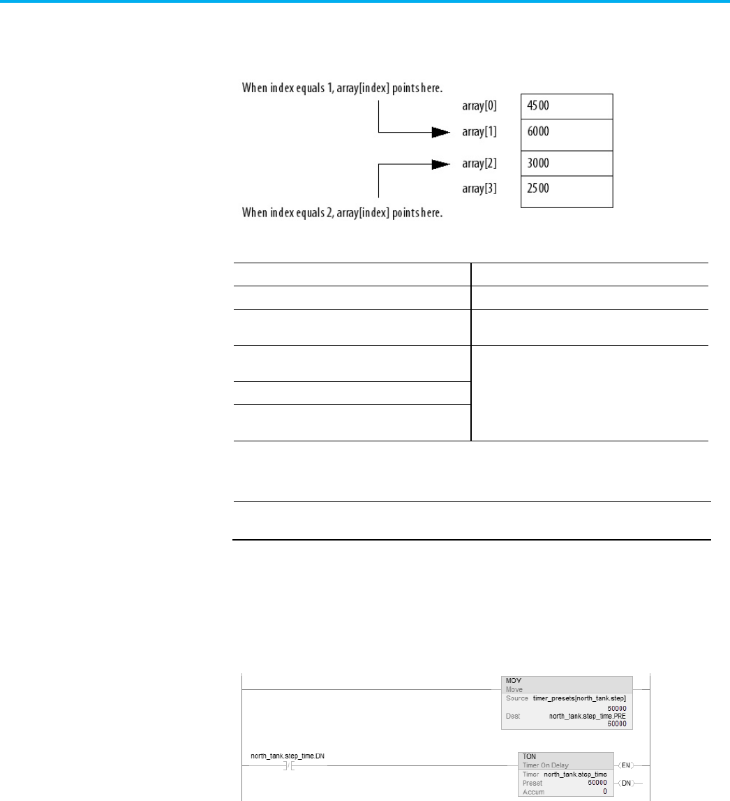
This example loads a series of preset values into a timer, one value (array
element) at a time.
EXAMPLE
Step through an array.
The timer_presets array stores a series of preset values for the timer in the
next rung. The north_tank.step tag points to which element of the array to
use. For example, when north_tank.step equals 0, the instruction loads
timer_presets[0] into the timer (60,000 ms).
Indirect addresses

Chapter 2 Organize tags
48 Rockwell Automation Publication 1756-PM004L-EN-P - November 2023
When north_tank.step_time is done, the rung increments north_tank.step to
the next number and that element of the timer_presets array loads into the
timer.
When north_tank.step exceeds the size of the array, the rung resets the tag to
start at the first element in the array. (The array contains elements 0–3.)
You can also use an expression to specify the subscript of an array.
• An expression uses operators, such as + or -, to calculate a value.
• The controller computes the result of the expression and uses it as the
array subscript.
You can use these operators to specify the subscript of an array.
Format your expressions as shown in this table.
If the operator requires
Use this format
Example
One value (tag or expression)
operator(value)
ABS(tag_a)
Two values (tags, constants, or expressions)
value_a operator value_b
•
tag_b + 5
• tag_c AND tag_d
• (tag_e ** 2) MOD (tag_f / tag_g)
Every instruction generates a major fault if the array subscript is out of range.
Transitional instructions also generate a major fault even if the rung is false.
The controller checks the array subscript in these instructions even if the rung
is false.
Expressions
Array subscript out of range

Chapter 2 Organize tags
Rockwell Automation Publication 1756-PM004L-EN-P - November 2023 49
Example
For more information on handling major faults, refer to the Logix 5000
Controllers Major and Minor Faults Programming Manual, publication no.
1756-PM014.
The table outlines the four types of tags and their descriptions.
IMPORTANT
The Logix Designer application automatically assigns what are called pass-through
descriptions of the created tags as an option.
Tag
Description
Base
When creating a tag without specifying a tag type, the Logix Designer application automatically
assigns the tag a default type of Base. Use base tags to create internal data storage and
document tag descriptions.
Alias
Use alias tags to assign unique names to an existing tag, structure tag member, or bit. In the
description of your alias tag, you can describe the tag that your alias tag references.
Produced
A produced tag refers to a tag that is consumed by another controller. In the description of your
produced tag, you can describe the remote controllers that you want to make your produced tag
available through controller-to-controller messaging.
Consumed A consumed tag refers to a tag that is produced by another controller and whose data you want
to use in your controller. In the description of your consumed tag, you can describe how you want
to use a produced tag’s data or the data-producing controller.
With version 17 and later of the Logix Designer application, you have the
option to display project documentation variables for any supported localized
language, such as:
• Component descriptions in tags, routines, programs, equipment
phases, equipment sequences, user-defined data types, and Add-On
Instructions.
Tag documentation
Project documentation

Chapter 2 Organize tags
50 Rockwell Automation Publication 1756-PM004L-EN-P - November 2023
• Engineering units and state identifiers added to tags, user-defined
data types, or Add-On Instructions.
• Trends.
• Controllers.
• Alarm messages (in configuration of ALARM_ANALOG and
ALARM_DIGITAL tags).
• Tasks.
• Property descriptions for a module in the Controller Organizer.
• Rung comments, Sequential Function Chart text boxes, and Function
Block Diagram text boxes.
You can store project documentation for multiple languages in a single project
file rather than in language-specific project files. You define all the localized
languages that the project supports and set the current, default, and optional
custom localized language. The application uses the default language if the
current language's content is blank for a particular component of the project.
H owever, you can use a custom language to tailor documentation to a specific
type of project file user.
Enter the localized descriptions in your Logix Designer project, either when
programming in that language or by using the import/export utility to
translate the documentation off-line and then import it back into the project.
Once you enable documentation languages in the Logix Designer application,
you can dynamically switch between languages as you use the application.
For more information on enabling a project to support multiple translations
of project documentation, see the online help.
Rockwell Automation Publication 1756-PM004L-EN-P - November 2023 51
Chapter 3
Force I/O
Use a force to override data that your logic either uses or produces. For
example, use forces to:
• Test and debug your logic.
• Check wiring to an output device.
• Temporarily keep your process functioning when an input device has
failed.
Use forces only as a temporary measure. They are not intended to be a
permanent part of your application.
When you use forces, take these precautions.
ATTENTION: Forcing can cause unexpected machine motion that could injure personnel. Before you
use a force, determine how the force affects your machine or process and keep personnel away from
the machine area.
• Enabling I/O forces causes input, output, produced, or consumed values to change.
• Enabling SFC forces causes your machine or process to go to a different state or phase.
• Removing forces may still leave forces in the enabled state.
• If forces are enabled and you install a force, the new force immediately takes effect.
E nable forces for a force to take effect. Only enable and disable forces at the
controller level.
• Enable I /O forces and SFC forces separately or at the same time.
• E nable or disable forces for a specific module, tag collection, or tag
element.
IMPORTANT
When downloading a project that has forces enabled, the application prompts to
enable or disable forces after the download completes.
When forces are in effect (enabled), a appears next to the forced
element.
To stop the effect of a force and let the project execute as programmed,
disable or remove the force.
• Disable or remove I /O and SFC forces at the same time or separately.
• Removing a force on an alias tag also removes the force on the
base tag.
Introduction
Precautions
Enable forces
Disable or remove a force

Chapter 3 Force I/O
52 Rockwell Automation Publication 1756-PM004L-EN-P - November 2023
ATTENTION:
Changes to forces can cause unexpected machine motion that could injure
personnel. Before you disable or remove forces, determine how the change affects your
machine or process and keep personnel away from the machine area.
Before you use a force, determine the status of forces for the controller. You
can check force status.
To determine status
Use any of the following
I/O forces
•
Online toolbar
• FORCE status indicator
• GSV instruction
SFC forces
Online toolbar
The Online toolbar shows the status of forces. It shows the status of I/O forces
and SFC forces separately.
This
Means
Enabled • If the project contains any forces of this type, they
are
overriding your
logic.
• If you add a force of this type, the new force immediately takes effect
Disabled Forces of this type are inactive. If the project contains any forces of this type,
they are not overriding your logic.
Installed
At least one force of this type exists in the project.
None Installed
No forces of this type exist in the project.
If your controller has a FORCE Status Indicator, use it to determine the status
of any I /O forces.
IMPORTANT
The FORCE Status Indicator shows only the status of I/O forces. It does not show that status
of SFC forces.
FORCE Status Indicator
Then
Off
•
No tags contain force values.
• I/O forces are inactive (disabled).
Flashing • At least one tag contains a force value.
• I/O forces are inactive (disabled).
Solid
•
I/O forces are active (enabled).
• Force values may or may not exist.
Check force status
Force status indicator

Chapter 3 Force I/O
Rockwell Automation Publication 1756-PM004L-EN-P - November 2023 53
This ladder rung shows how to use a GSV instruction to get the status of
forces.
IMPORTANT
The ForceStatus attribute shows only the status of I/O forces. It does not show the status of
SFC forces.
Use the following table where Force_Status is a DI NT tag.
To determine if
Examine this bit
For this value
Forces are installed
0
1
No forces are installed
0
0
Forces are enabled
1
1
Forces are disabled
1
0
Use an I /O force to override:
• An input value from another controller (that is, a consumed tag).
• An input value from an input device.
• Logic and specify an output value for another controller (that is, a
produced tag).
• Logic and specify the state of an output device.
IMPORTANT
•
Forcing increases logic execution time. The more values forced, the longer it takes
to execute the logic.
• I/O forces are held by the controller and not by the programming workstation.
Forces remain even if the programming workstation is disconnected.
Use these guidelines when forcing an I /O value.
• Force all I/O data, except for configuration data.
• If the tag is an array or structure, such as an I/O tag, force a BOOL,
SI NT, I NT, DI NT, or R E AL element or member.
• I f the data value is a SI NT, I NT, or DI NT, force the entire value or force
individual bits within the value. Individual bits can have a force status
of:
• No force
• Force on
• Force off
• Force an alias to an I/O structure member, produced tag, or consumed
tag.
• An alias tag shares the same data value as its base tag, so forcing an
alias tag also forces the associated base tag.
GSV instruction
When to use I/O force

Chapter 3 Force I/O
54 Rockwell Automation Publication 1756-PM004L-EN-P - November 2023
• Removing a force from an alias tag removes the force from the
associated base tag.
• I f a produced tag is also Constant, it cannot use forces.
• If a produced tag is forced, it cannot be a Constant.
Forcing an input or consumed tag:
• Overrides the value regardless of the value of the physical device or
produced tag.
• Does not affect the value received by other controllers monitoring that
input or produced tag.
Forcing an output or produced tag overrides the logic for the physical device
or other controller. Other controllers monitoring that output module in a
listen-only capacity also see the forced value.
To override an input value, output value, produced tag, or consumed tag, use
an I /O force.
ATTENTION: Forcing can cause unexpected machine motion that could injure personnel. Before using a
force, determine how the force affects the machine or process and keep personnel away from the
machine area.
• Enabling I/O forces causes input, output, produced, or consumed values to change.
If forces are enabled and you install a force, the new force immediately takes effect.
To add an I/O force
1. Check the state of the I/O Forces status indicator.
If
Then note
Off No I/O forces currently exist.
Flashing
No I/O forces are active. But at least one force already exists in the project. When enabling I/O
forces,
all
existing I/O forces also take effect.
Solid
I/O forces are enabled (active). When installing (adding) a force, it immediately takes effect.
2. Open the routine that contains the tag to force.
3. Right-click the tag and then select Monitor.
I f necessary, expand the tag to show the value to force (that is, BOOL
value of a DI NT tag).
4. I nstall the force value.
Force an input value
Force an output value
Add an I/O force

Chapter 3 Force I/O
Rockwell Automation Publication 1756-PM004L-EN-P - November 2023 55
To force a
Do this
BOOL value
Right-click tag and then select Force On or Force Off.
Non-BOOL value
In Force Mask, type the value to force the tag. Press Enter.
5. Verify that I /O forces are enabled (see step 1). I f they are not, select
Menu > Logic > I/O Forcing > Enable All I/O Forces, and then select
Yes to confirm.
Remove forces, or disable them.
ATTENTION: Changes to forces can cause unexpected machine motion that could injure personnel.
Before disabling or removing forces, determine how the change affects the machine or process and
keep personnel away from the machine area.
This section describes how to remove and disable forces.
To
And
Then
Stop an individual force
Leave other forces enabled and in
effect
Remove an Individual Force
Stop all I/O forces but leave all SFC
forces active
Leave the I/O forces in the project Disable All I/O Forces
Remove the I/O forces from the
project
Remove All I/O Forces
You can remove an individual force.
ATTENTION: ATTENTION: If you remove an individual force, forces remain in the enabled state and any
new force immediately takes effect.
ATTENTION:
Before you remove a force, determine how the change affects your machine or process
and keep personnel away from the machine area.
To remove an individual force
1. Open the routine that contains the force that you want to remove.
2. Determine the language of the routine.
If
Then
SFC
Go to step 4.
Ladder logic
Go to step 4.
Function block
Go to step 3.
Structured text
Go to step 3.
3. Right-click a tag that has the force and then click Monitor.
If necessary, expand the tag to show the value that is forced, for
example, BOOL value of a DI NT tag.
Remove or disable forces
Remove an individual force

Chapter 3 Force I/O
56 Rockwell Automation Publication 1756-PM004L-EN-P - November 2023
4. Right-click a tag or element that has the force and then select Remove
Force.
To disable, on the Menu bar, select Logic > I/O Forcing > Disable All I/O
Forces. Select Yes to confirm.
To remove, on the Menu bar, select Logic > I/O Forcing > Remove All I/O
Forces. Select Yes to confirm.
Disable all I/O forces
Remove all I/O forces

Rockwell Automation Publication 1756-PM004L-EN-P - November 2023 57
Chapter 4
Data access control
I n version 18 or later of the Logix Designer application, there are tag
attributes that allow you to control access to tag data. These attributes are:
• External Access
• Constant
• OPC UA
The External Access attribute controls how external applications, such as
HMI s, can access tags. I t has possible values of Read/Write, Read Only, and
None. See Configure external access.
The Constant attribute value determines if controller logic can change a tag.
Also, by using FactoryTalk Security software, it is possible to control which
users can change tags designated as constants in the Logix Designer
application. See Constant value tags for more information on the Constant
attribute.
The OPC UA attribute determines the access that external OPC UA clients
have to tags.
By using these attributes, you can help safeguard tag data by preventing
unwanted changes to tag values. Also, by reducing the number of tags exposed
to external applications, you can reduce the time required to develop HMI
screens.
Use the External Access attribute to control how external applications and
devices access tags.
Using external access reduces the number of tags for an application that
appear when you reference them in applications or devices. I t can also
improve system performance by reducing the number of tags RSLinx has to
maintain, scan, and cache. Reducing the number of externally accessible tags
can improve the performance of the RSLinx data server and other related
applications.
External applications and devices include:
• RSLinx Classic and FactoryTalk Linx software.
• Other Logix controllers.
• PanelView terminals.
• PLC/SLC controllers.
• FactoryTalk Historian software.
Introduction
External access

Chapter 4 Data access control
58 Rockwell Automation Publication 1756-PM004L-EN-P - November 2023
• Other third-party software.
Configure external access from a menu when creating a new tag or data type.
Change that value just like other tag attributes and make these changes
throughout the application. For example, make the changes in the
User-defined Data Type Editor, New Tag dialog box, and the Tag Properties
di alog box.
External Access Settings
Description
Read/Write
External applications and devices have full access to the tag and can read
and change the tag’s value.
Read Only External applications can read, but cannot change, the tag’s value.
None
External applications cannot read or change the tag’s value.
IMPORTANT
• The Logix Designer application has full access to all tags, regardless of their external
access settings. External access applies to all program, controller, and Add-On Instruction
scoped tags.
• If the controller is in safety locked mode, only the safety tags are disabled from being
accessed. The standard tags have the same behavior as in the unlocked mode.
Choose one of three options: Read/Write, Read Only, or None from the
External Access list on the Logix Designer dialog boxes.
• New Tag (See Configure external access in the New Tag dialog box)
• Tag Properties (See Set up external access in the Tag Properties dialog box)
The default value in the External Access list depends on the usage and type of
the tag. The table describes the values.
If the tag is
Default value is
Alias
Same as its target. See the Important note following this table.
Controller or program scoped and equipment
phase input parameters
The initial value is Read/Write.
Thereafter, when creating a new tag, the default external access
tag keeps the value of the previous choice.
(1)
Equipment phase output parameters The initial value is
Read Only
.
Thereafter, when creating a new tag, the default external access
tag keeps the value of the previous choice.
(1)
1. The external access default value for tag creation is stored for each Windows login account.
IMPORTANT
For alias type tags, the External Access list is unavailable. You cannot change the
external access of an alias tag. However, the
External Access
list updates its value to
be the same as the external access of the base target.
See Find a base tag with Go To for procedures to locate the base tag for an alias.
See External access availability for additional tag considerations.
See also
Configure external access in the New Tag dialog box on page 59
Configure external access
External access options

Chapter 4 Data access control
Rockwell Automation Publication 1756-PM004L-EN-P - November 2023 59
Set up external access in the Tag Properties dialog box on page 60
Find a base tag with Go To on page 61
External access availability on page 62
Create these types of tags in the New Tag di alog box.
• Base
• Alias
• Produced
• Consumed
The parameters on the dialog box depend on the type of tag. For tag
descriptions, see Tag type.
To configure external access in the New Tag dialog box
Choose the external access attribute for a new tag in the External Access list
on the New Tag dialog box. Follow these steps.
1. In the Controller Organizer, right-click Controller Tags and then
select New Tag.
2. In New Tag, in the Type list, choose a tag type.
3. In the External Access list, choose an external access option.
4. Select OK.
As shown in this example, the External Access list is unavailable for an alias
tag.
There may be many alias tags in a program. To locate an associated base tag to
assign an external access, use the Go To feature. See Find a base tag with Got To
for details.
For other tag considerations, see External access availability.
The Connection button (next to the Type box) becomes active when you select
either a produced or consumed tag type. The button displays a dialog box to
set up produced and consumed tag connections. See the Logix 5000 Controller
Produced and Consumed Tags Programming Manual, publication no. 1756-PM011.
Configure external access in
the New Tag dialog box

Chapter 4 Data access control
60 Rockwell Automation Publication 1756-PM004L-EN-P - November 2023
See also
Tag type on page 22
Find a base tag with Go To on page 61
External access availability on page 62
Logix 5000 Controllers Produced and Consumed Tags Programming
Manual, publication no. 1756-PM011
Use the Tag Properties dialog box to edit properties of existing tags. You can
change tag attributes and change tag types.
Follow these steps to choose an external access option for an existing tag.
To set up external access in the Tag Properties dialog box
1. In the Tag Editor, right-click a tag and then select Edit (tag name)
Properties.
2. In Tag Properties, in the Type list, choose a tag type.
3. In the External Access list, choose an external access option.
The External Access list is unavailable for an alias tag. I f a tag is a
module tag, the only external access option is Read/Write.
See External access availability for other considerations.
4. Select OK.
See also
External access availability on page 62
View the external access status of a tag in the Tag Editor. The External Access
column displays the tag as Read/Write, Read Only, or None.
Set up external access in
the Tag Properties dialog
box
View and select external
access status on the Tag
Editor

Chapter 4 Data access control
Rockwell Automation Publication 1756-PM004L-EN-P - November 2023 61
To view and select external access status on the Tag Editor
1. Select multiple rows and set the external access at one time on the Tag
E ditor.
To select multiple individual rows, hold down the Ctrl key and select
the desired rows.
2. Right-click a selected tag, and then select Set External Access for (tag
name) to select an external access option.
This updates the external access for all highlighted rows that are
enabled for changing external access.
See External access availability for considerations when the External Access
column is unavailable.
See also
External access availability on page 62
You can only change the external access setting of an alias tag through its
base tag. The Go To command on the Search menu of the Logix Designer
application is a convenient way to find the base tag among all the
cross-reference records.
Find a base tag with Go To
1. In the Tag Editor select the alias tag, and then on the Logix Designer
application Menu bar, select Search > Go To.
You can also right-click the alias tag and then select Go To.
2. In the Go To dialog box, in the Go to what list, choose Base Tag.
Find a base tag with Go To

Chapter 4 Data access control
62 Rockwell Automation Publication 1756-PM004L-EN-P - November 2023
The Go To box displays the target of the alias tag. If there is an alias
chain, all alias tags in this chain appear in the Go to list.
3. In the Go to list, choose a target of the alias tag.
4. Select Go To.
The target is located with a black box around it.
The table describes the conditions in which the External Access list is
unavailable.
IMPORTANT
The External Access list is always unavailable for any tag whose data type is Alarm Analog or
Alarm Digital
. The external access status is always
Read/Write
for these data types.
Dialog Box/Window
Considerations
New Tag
The External Access list is unavailable if:
• The tag is an alias tag.
• The controller is user locked online.
Changing the tag type from base to alias also makes the
External Access
list unavailable. If you select a target for an alias tag in the
Alias For
list, the
External Access
list remains unavailable, but the external access value for the target tag appears in the
External Access
list.
You can only change the external access value of an alias tag through its base tag.
Tag Properties
The External Access list is unavailable if:
• You do not have permission to change the external access settings.
• The redundancy controller is in any state that does not allow changes.
• The controller is user-locked online from another computer.
• The controller is safety-locked and the tag is a safety tag.
• The tag scope is an equipment phase and the equipment phase feature is not activated in the current license.
• The tag is an alias tag.
• The controller is in hard-run mode.
External access availability

Chapter 4 Data access control
Rockwell Automation Publication 1756-PM004L-EN-P - November 2023 63
Dialog Box/Window
Considerations
Tag Editor
The External Access list is unavailable if:
• You do not have permission to change the external access settings.
• The redundancy controller is in any state that does not allow changes.
• The controller is user-locked online.
• The controller is safety-locked and the tag is a safety tag. Only the safety tags’
External Access
list is disabled.
• The tag scope is an equipment phase and the equipment phase feature is not activated in the current license.
• The tag is an alias tag.
• The controller is in hard-run mode.
• The row represents an expanded array dimension, bit, or data member.
For tags of
Predefined
(Atomic and Structural),
Module-Defined
Data Types and
String
, all of these tag members have the same external
access level because:
• They are all hard-coded to
Read/Write
and you can only view, not change, this value. You also cannot change external access for the data
type members.
• An external access change on the tag results in an update on all tag members.
For array tags, all elements:
• Must have the same external access level.
• Of all data members for predefined or module-defined data types have the same external access setting.
• Of each data member for user-defined type (UDT) and Add-On Instruction have the more restrictive external access setting between the
element external access setting and the external access setting of the member in the type definition.
You select the external access options for a tag—Read/Write (default), Read
Only, or None—from the Data Type Editor Properties pane.
1. In the Controller Organizer, right-click the data type and then select
Properties.
2. I n the Data Type editor, select the Properties tab to display the
Properties pane. Select the pushpin icon to keep the Properties pane
open.
User-defined type
considerations

Chapter 4 Data access control
64 Rockwell Automation Publication 1756-PM004L-EN-P - November 2023
3. In the External Access list, choose the external access option.
Three external access rules apply for members of User-defined data types.
• You can only set external access for the top members of that
User-defined data type. External Access boxes for the child-members
are unavailable on the User-defined Data Type Editor.
• I f the member’s data type is Predefined structural, Module-defined, or
String, you cannot set external access of child-members. The external
access level of the parent member applies to its child-members.
• I f the member’s data type is User-defined and the child-member has a
different external access level from its parent, the more restrictive
external access level applies to the child-members.
This table describes the conditions in which the External Access column is
unavailable.
To pick
Considerations
Change
existing
data type
The External Access column is unavailable if:
You do not have permission to change the
external access settings.
( 1)
The redundancy controller is in any state that
does not allow changes.
The data type is applied to tags and the
controller is onli ne.
Tip: Data type size is not affected by the
external access attribute.
Predefine
d,
module-d
efined,
Strings
type
The External Access column is always visible
but unavailable. The Set External Access entry
is added to the bottom of the row header
context menu, but it is always unavailable.
1.If you have User-defined Data Type Modify permission, you also can modify external access of a User-defined data type.
You can use external access settings with parameters and local tags of Add-On
Instructions. For example, if you define an input parameter with external
access of read only, the member that represents that parameter in the Add-On
Instruction data type cannot be written.
This table describes the external access options for various Add-On
Instruction parameters and tags.
Add-0n Instruction Parameters and Tags
External Access Options
Local tag
Read/Write
Read Only
None
Input parameter
Output parameter
Add-on instructions external
access considerations

Chapter 4 Data access control
Rockwell Automation Publication 1756-PM004L-EN-P - November 2023 65
Add-0n Instruction Parameters and Tags
External Access Options
EnableIn parameter
Read Only
EnableOut parameter
InOut parameter
Not Applicable
You can choose the external access for an Add-On Instruction tag from the list
on the New Add-On Instruction Parameter or Local Tag dialog box or from
the External Access column on the Tag Editor.
You can configure the external access of an Add-On Instruction’s parameters
and local tags in the Add-On Instruction Definition dialog box and on the
Add-On Instruction Parameters and Local Tags di alog boxes.
For alias parameters, the external access type is equal to the type configured
for the base local tag.
Dialog Box/Window
Considerations
New Add-On Instruction
Parameter or Local Tag
If the current usage is:
• Input parameter, then the
External Access
list is available and the displayed value is your last selection when creating an equipment phase
input parameter or Add-On Instruction input parameter.
• Output parameter, then the
External Access
list is available and the displayed value is your last selection when creating an equipment phase
output parameter or Add-On Instruction output parameter.
• InOut parameter, then the
External Access
list is unavailable and blank.
• Local tag, then the
External Access
list is unavailable and the displayed value is None.
Parameters/Local Tag
Properties
No change is applied to the External Access list if you switch the usage among Input parameter, Output parameter or Local Tag, except when
the usage is
Local Tag
, then the list is unavailable.
If you change the usage from
InOut
parameter to:
• Input or output parameter, then the
External Access
list is available and your last selection for creating an equipment phase/Add-On
Instruction input parameter or an equipment phase/Add-On Instruction output parameter is displayed accordingly.
• Local tag, then the external access is updated to
None
and the list is unavailable.
The
External Access
list also is unavailable if:
• You do not have permission to change external access settings.
(1)
• The controller is online.
• The tag is an alias tag.
• The Add-On Instruction is in Source Protection mode.

Chapter 4 Data access control
66 Rockwell Automation Publication 1756-PM004L-EN-P - November 2023
Dialog Box/Window
Considerations
Add-On Instruction
Definition - Parameters
Tab
The External Access column is unavailable for:
• InOut parameters, for which there are no external access options.
• EnableIn and EnableOut parameters, which default to
Read Only
.
The
External Access
column is unavailable when:
• You do not have permission to change the external access settings.
(1)
• The controller is online.
• The tag is an alias tag.
• The Add-On Instruction is in Source Protection mode.
• The row represents an expanded bit, or data member.
For new parameters, changing
Usage
changes the
External Access
default:
• To
Read/Write
for
Input Parameter
, equipment phase input parameter, and Add-On Instruction input parameter.
• To
Read Only
for
Output Parameter
, for equipment phase output parameter, and Add-On Instruction output parameter.
• To blank and unavailable for
InOut Parameter
.
Changing external access attributes cause:
• An error message if you change a tag from
Input
or
Output Parameter
to
InOut Parameter
and the present attribute is either
Read/Write
, or
Read Only
.
• No change if you switch between
Input Parameter
and
Output Parameter
.
• The value of the external access updates to the new target for an alias.
Add-On Instruction
Definition - Local Tags Tab
The External Access column is unavailable if:
• You do not have permission to change external access settings.
(1)
• The controller is online.
• The Add-On Instruction is in Source Protection mode.
• The row represents an expanded array dimension, bit, or data member.
Add-On Instruction Edit
Tags
Note: External access is not applicable for InOut parameters because they are just references until invoked.
The
External Access
column is unavailable for:
• EnableIn and EnableOut parameters, which default to
Read Only
.
The
External Access
column is unavailable when:
• You do not have permission to change the external access settings.
(1)
• The controller is online.
• The tag is an alias tag.
• The Add-On Instruction is in Source Protection mode.
• The row represents an expanded array dimension, bit, or data member.
For new parameters, changing
Usage
changes the
External Access
default:
• To
Read/Write
for
Input Parameter
, equipment phase input parameter, and Add-On Instruction input parameter.
• To
Read Only
for
Output Parameter
, for equipment phase output parameter, and Add-On Instruction output parameter.
• To blank and unavailable for
InOut Parameter
.
• To
None
and unavailable for
Local Tag
.
Changing the external access attribute causes:
• A warning message if you change a tag from
Input Parameter
or
Output Parameter
to
InOut Parameter
and the parameter attribute is either
Read/Write
, or
Read Only
.
• No change if you switch between
Input Parameter
or
Output Parameter
and
Local tag
.
Finally, the external access value updates to the value from the new target if you change the target for an alias for an Input or Output
parameter.
1.If you have User-defined Data Type Modify permission, you also can change the external access for a User-defined data type.
Only tags with external access settings of Read/Write or Read Only can be
mapped to a PLC-2 controller and PLC-5/SLC controllers.
1. In the PLC-2 or PLC-5/SLC Mapping dialog box, type a file number.
2. Choose a tag from the Name list. Only eligible tags that are set to either
Read/Write or Read Only appear in the menu.
I f you manually type the name of a tag whose external access is set to
None, an error message appears.
3. Select OK.
Tag mapping considerations

Chapter 4 Data access control
Rockwell Automation Publication 1756-PM004L-EN-P - November 2023 67
The Logix Designer application preforms a check to verify an imported
program file has a valid external access value. A default value is assigned to
unspecified tags that are imported from programs created in the Logix
Designer application earlier than version 18.
An error message appears in the Logix Designer application for imported files
that contain tags with any value other than Read/Write, Read Only, and
None.
Object Name
Default External Access
Controller and program-scoped standard tags
Read/Write
All safety tags
Read Only
Add-on Instruction local tags
Read/Write
Add-on Instruction Input parameters
Read/Write
Add-on Instruction Output, EnableIn and EnableOut parameters
Read Only
Add-on Instruction InOut parameters
N/A
Equipment phase output parameters
Read Only
Members of all data types
Read/Write
The OPC UA Access property setting allows you to specify the level of access
(Read-only, Read/write, or None) that OPC UA clients have to tags. This
property setting applies to tags exposed to OPC UA clients directly from the
controller. Configure OPC UA access when you create a tag. After you create a
tag, you can modify the tag's OPC UA access. You can configure OPC UA
Access for controller and program-scoped tags.
Tip: OPC UA access is inoperable in redundant systems.
OPC UA Access setting
Description
Read/write External OPC UA clients have full access to the tag and can read and change the tag's value.
Read-only External OPC UA clients can read, but cannot change, the tag's value.
None
External OPC UA clients cannot read or change the tag's value.
For constant tags, OPC UA server access is limited to None and Read-only.
For output parameters, OPC UA server access is limited to None and
Read-only.
For I nOut parameters, OPC UA server access is limited to Read/write.
For safety tags, there are certain limitations:
• When the controller is online, it is not possible to edit the OPC UA
Access of a safety tag.
Imported tag behavior
OPC UA Access

Chapter 4 Data access control
68 Rockwell Automation Publication 1756-PM004L-EN-P - November 2023
• When the controller is online, it is not possible to delete the safety tag
if the tag is published in the OPC UA server.
• When the controller is online, it is not possible to rename a safety tag if
the tag is published in the OPC UA server.
• When the controller is online, it is not possible to rename safety
programs that expose safety tags in the OPC UA server or safety
programs that are parents of such safety programs.
• When creating a safety tag when the controller is online, None is the
only level of access that is available for selection.
• Safety tags only have Read-only or None levels of access.
The OPC UA Access property setting allows you to specify the level of access
that external OPC UA clients have to tags.
Configure OPC UA access from a menu when creating a new tag.
OPC UA Access Settings
Description
Read/write
External OPC UA clients have full access to the tag and can read and
change the tag's value.
Read Only External OPC UA clients can read but cannot change the tag's value.
None
External OPC UA clients cannot read or change the tag’s value.
Tip: OPC UA access is fully independent of External Access for the OPC UA server embedded in Logix
Designer controllers. In case of the OPC UA server in FactoyrTalk Linx Gateway, the OPC UA access depends
on External Access.
For OPC UA Access, choose one of three options: Read/write, Read-only, or
None.
If the tag is
Default value
Alias Same as the alias target.
If a target tag does not exist, the OPC UA Access field is empty.
Controller or program scoped
None
Equipment phase and Equipment Sequence
None
Use Tag Properties to edit the properties of tags.
1. In Tag Editor, right-click a tag and then select Edit (tag name)
Properties.
2. In Tag Properties, in the Type list, choose a tag type.
3. In OPC UA Access, choose an access option. The OPC UA Access list is
unavailable for an alias tag. If a tag is a module tag, the only external
access option is Read/write.
4. Select OK.
Configure OPC UA Access
OPC UA Access options
Configure OPC UA Access in
the Tag Properties dialog
box

Chapter 4 Data access control
Rockwell Automation Publication 1756-PM004L-EN-P - November 2023 69
Configure the OPC UA Access of a tag in the Tag Editor.
Perform one of these steps:
• Select multiple rows and then set the OPC UA Access.
• Select multiple individual rows by pressing Ctrl while selecting rows.
• Right-click a selected tag and then select OPC UA Access for (tag
name). This action updates the OPC UA Access for all highlighted rows
that are enabled for changing OPC UA Access.
This table contains the conditions in which OPC UA Access options are
unavailable.
View and select OPC UA
Access status on the Tag
Editor
OPC UA Access availability

Chapter 4 Data access control
70 Rockwell Automation Publication 1756-PM004L-EN-P - November 2023
Dialog Box/Window
Considerations
New Tag The
OPC UA Access
list is unavailable if:
• The tag is an alias tag.
• The controller is user -ocked online from another computer.
Changing the tag type from base to alias also makes the
OPC UA Access
list unavailable. If you select a target for an alias tag in the
Alias For
list, the
OPC UA Access
list remains unavailable, but the OPC UA Access value for the target tag appears in the
OPC UA Access
list.
You can only change the OPC UA Access value of an alias tag through its base tag.
Tag Properties
The OPC UA Access list is unavailable if:
• You do not have permission to change the OPC UA Access settings.
• The redundancy controller is in any state that does not allow changes.
• The controller is user-locked online from another computer.
• The tag is a safety tag and the controller is safety-locked or a project contains a safety signature.
• The tag scope is an equipment phase and the equipment phase feature is not activated in the current license.
• The tag scope is an equipment sequence and the equipment sequence feature is not activated in the current license.
• The tag is an alias tag.
• The controller is in hard-run mode.
Tag Editor
The OPC UA Access list is unavailable if:
• You do not have permission to change the OPC UA Access settings.
• The redundancy controller is in any state that does not allow changes.
• The controller is user-locked online from another computer.
• The controller is safety-locked or a project contains a safety signature and the tag is a safety tag. As a result, safety tags as a whole are not
editable.
• The tag scope is an equipment phase and the equipment phase feature is not activated in the current license.
• The tag is an alias tag.
• The controller is in hard-run mode.
• The row represents an expanded array dimension, bit, or data member.
OPC UA access can only bet set on a tag's level, and not on the tag's subitems. The subitems of tags inherit their properties from the parent
tag. As such, it is not possible to set OPC UA access on:
• arrays
• any structure members
• bit members
You can only map tags with OPC UA Access settings of Read/write or
Read-only to a PLC-2 controller and to PLC-5/SLC controllers.
1. In PLC-2 or PLC-5/SLC Mapping, type a file number.
2. In Name, choose a tag. Only tags that are set to either Read/write or
Read-only appear.
3. Select OK.
Mapping tags to controllers
for OPC UA Access

Chapter 4 Data access control
Rockwell Automation Publication 1756-PM004L-EN-P - November 2023 71
The Logix Designer application performs a check to verify that an imported
program file has a valid OPC UA Access value. A default value is assigned to
unspecified tags that are imported from programs created in the Logix
Designer application earlier than version 36.
An error message appears in the Logix Designer application for imported files
that contain tags with any value other than Read/write, Read-only, and None.
I n version 18 and later of the Logix Designer application, you can designate
tags as constants to protect them from being changed programmatically by:
• The controller programming application
• Logic in the controller
The tags that you cannot designate as constants are User-defined type
member s, Add-On I nstruction input and output parameters, and local tags.
Make a tag a constant value tag by selecting the Constant check box on the tag
creation dialog boxes and tag editor/monitor windows.
Use FactoryTalk security to control who is permitted to change values of
constants and who can change the constant attribute of a tag. To change the
value of a constant, you must have the Tag: Modify Constant Tag Values
permission. To change the constant attribute of a tag, you must have the Tag:
Modify Constant Property permission.
For details on setting permissions, see the FactoryTalk Security System
Configuration Guide, publication no. FTSEC-QS001.
For an alias tag, the default constant setting of this tag is the same as its target
tag. For all other conditions, the default value is unchecked, indicating the tag
is not a constant value tag.
When you designate an InOut parameter as a constant, it cannot be written to
within the Add-On Instruction.
Tip: You cannot pass a constant value tag as an argument to an Output parameter of an Add-On
Instruction. You cannot pass a constant tag to an InOut parameter that is not also designated as a constant
value.
See also
FactoryTalk Security System Configuration Guide, publication no.
FTSEC-QS001
This section describes the various ways you can configure a constant attribute
for a tag.
Imported tag behavior for
OPC UA Access
Constant value tags
Configure constant tags

Chapter 4 Data access control
72 Rockwell Automation Publication 1756-PM004L-EN-P - November 2023
Follow these steps to configure a tag as a constant.
To set up a constant in the New Tag dialog box
1. On the Controller Organizer, right-click Controller Tags and then
select New Tag.
2. In New Tag, in the Type list, choose a tag type.
3. Select Constant.
4. Select Create.
See Constant check box availability for considerations.
See also
Constant check box availability on page 74
Follow these steps to designate a tag as a constant on the Tag Properties
di alog box.
To configure a constant in the Tag Properties dialog box
1. On the Tag Editor, right-click a tag and then select Edit (tag name)
Properties.
2. In Parameter/Local Tag Properties, select Constant check box.
3. Select OK.
See Constant check box availability for considerations.
Set up a constant in the New
Tag dialog box
Configure a constant in the
Tag Properties dialog box

Chapter 4 Data access control
Rockwell Automation Publication 1756-PM004L-EN-P - November 2023 73
See also
Constant check box availability on page 74
The Constant column in the Tag Editor provides a way to designate tags that
cannot be modified in the Logix Designer program. The Constant property
applies to an entire tag; all members of the tag take on the same setting. The
Constant column cells are blank for members of the constant tag.
To designate a constant in the Tag Editor
An error message appears when attempting to change the data type of a
constant tag to a data type that cannot be constant.
Follow these steps to add a constant value in the Tag Editor.
1. In the Controller Organizer, right-click Controller Tags and then
select Edit Tags.
2. I n the Tag Editor, select the check box in the Constant column.
IMPORTANT
In the Tag Monitor, the Constant setting for the tag appears in the same
Constant
column as
shown in the previous illustration. However, you cannot change the value.
The
Constant
column also is available on the Equipment Phase Tag Editor and Equipment
Phase Tag Monitor.
Designate a constant in the
Tag Editor

Chapter 4 Data access control
74 Rockwell Automation Publication 1756-PM004L-EN-P - November 2023
Use component tracking to determine whether tracked components have
been changed. The Logix Designer application creates an overall tracked value
to indicate the current state of tracked components.
Tip: Component tracking is supported only on CompactLogix 5370, ControlLogix 5570, Compact GuardLogix
5370, and GuardLogix 5570 controllers in version 30.00 of the Logix Designer application.
Tracked components and their current states appear in the Tracked
Components dialog box, which is accessible on the Controller Properties
dialog box - Security tab.
The recommended limit on the number of constant tags that can be tracked is
300. I f this limit is exceeded, there might be a noticeable impact on
performance in the Logix Designer application. W hen tracking a base tag or
an alias tag, the base tag and all alias tags are tracked.
Tip: To optimize performance, configure component tracking so that the tracked state value is calculated
on demand rather than at regular intervals.
For more information on component tracking, see the <LOGIX5K Controllers
Information and Status Programming Manual, publication no. 1756-PM015.
The FactoryTalk Security permission Tag: Modify Properties controls a user's
ability to change the tracking status for a constant tag.
To track a constant tag
Follow these instructions to enable tracking on an Add-On Instruction.
1. In the Tag Editor or the Data Monitor, highlight the constant tag to
track.
2. Right-click and select Include in tracking group.
3. To stop tracking a constant tag, right-click and select Include in
tracking group again.
See also
Logix 5000 Controllers I nformation and Status Programming Manual,
publication no. 1756-PM015
The state of the Constant check box depends on a number of conditions.
Track a constant tag
Constant check box
availability

Chapter 4 Data access control
Rockwell Automation Publication 1756-PM004L-EN-P - November 2023 75
Dialog Box/Window
Considerations
New Tag
The Constant check box is unavailable if:
• The tag is an alias tag.
• The Factory Talk Security action is not enabled for changing constant value property of a tag.
• You do not have permission to change tag properties (Factory Talk Security Tag Modify is denied.)
• The new tag is a consumed tag.
• The tag’s data type is not a data table-backed type.
• The tag is used in an Add-On Instruction as an input parameter, output parameter, or local tag.
• Redundancy controller is in any state that does not allow changes.
• The controller is safety-secured and the tag is a safety tag.
(1)
• If the tag scope is an equipment phase and the equipment phase feature is not activated in the current license.
• The controller is in hard-run mode.
• The Add-On Instruction is in Source Protection mode.
Tag Properties
Tag Editor
Same considerations apply as for New Tag (preceding row).
Tag Monitor
You can change the value of a constant tag in the Tag Monitor if you have both standard
Tag: Modify Values
permission and
Tag: Modify
Constant Tag Values
permission. You cannot change a constant value in any of the language editors or any other tag browser. The icon in
the
Value
column indicates that you are changing a constant value tag’s value. Any change to the values of a constant tag is recorded in the
Controller Log for future reference.
For controller logging, see the Logix 5000 Controllers Information and Status Programming Manual, publication no. 1756-PM015.
1.If the controller is in safety-locked mode, only the safety tags are unavailable, and the standard tags will have the same behavior
as in the unlocked mode. The
Constant check box is unavailable in the Tag Properties dialog box only if the tag is a safety tag.
See also
Logix 5000 Controllers I nformation and Status Programming Manual,
publication no. 1756-PM015
The Constant attribute applies only to InOut parameters. The default setting
of the property is not a Constant Value.
The Constant attribute does not apply to Input, Output, EnableIn and
E nableOut Add-On Instruction parameters. It does not apply to Add-On
Instruction Local tags.
If in an Add-On Instruction, you make an InOut parameter a constant, it
means that within the Add-On Instruction, nothing can write to that
parameter. The project fails verification if this type of write is attempted.
Appropriate usage of Constant tags is monitored by logic verification.
Add-on instructions
constant value
considerations

Index
Rockwell Automation Publication 1756-PM004L-EN-P - November 2023 77
Index
A
access
external 57
add extended properties to a tag 30
add extended properties to user-defined
data type 39
Add-On Instruction
constant value considerations 75
external access variables 65
address
assign indirect 47
tag 44
tag I/O module 14
alias
create 46
show/hide 46
use of 44
array
calculate subscript 48
create 34
index through 47
organize 25
overview 31
availability
constant value 74
external access 62, 63
B
base tag 61
buffer
I/O data 16
C
communication
format 11
ownership 11
I/O module 9
module I/O configuration 51
compatible
keying 13
configure
external access 58
connection
listen-only 11
overview 9
considerations
Add-On Instructions
constant value 75
external access 65
external access 62, 63
user-defined data type external access
63
constant
track constant tags 74
value
availability 74
dialog box 72
tag editor 73
tag properties 72
value configuration 71
value tags 71
controller
tags 22
use of 22
create
alias 46
tag 29
user-defined data type 38
D
data
block
See array (create) 31
I/O 14
table
See tag (organize) 51
type
choose 20
overview 20
structure 20
description
tag 41
user-defined data type 41
direct connection 11
disable
force 51
document
tag
description 41
user-defined data type 41
E
electronic keying
I/O 13
enable
force 51
exact match
keying 13

Index
78 Rockwell Automation Publication 1756-PM004L-EN-P - November 2023
expression
calculate array subscript 48
extended properties 20
adding extended properties to a
tag 30
user-defined data type 39
external
access 57
Add-On Instruction 65
availability 62, 63
configure 58
configure tag dialog 59
configure tag properties 60
options 58
user-defined data type considerations
63
view tag editor 60
F
file
See array 31
force
disable 51
enable 51
remove 51
function block diagram
force a value 51
G
global data
See scope 22
Go To 61
I
I/O module
buffer data 16
configuration 51
document
See alias 44
electronic keying 13
ownership 11
synchronize with logic 16
tag address 14
update period 9
index
See indirect address 47
indirect address 47
format 44
use of expression 48
K
keying
See electronic keying 13
L
ladder logic
force a value 51
override a value 51
local data
See scope 22
M
memory
allocation for tags 20
Min and Max for DINT, INT, LINT, SINT, and
REAL data types 30, 39
module
I/O configuration 51
N
name
guidelines for tag 25
reuse of tag name 22
O
OPC UA Access 68
ownership
I/O module 11
P
pass-through description 41
program
parameters 9, 16, 22, 24
tags 22
program parameters 9, 16, 22, 24
project documentation 50
R
rack-optimized connection 11
remove
force 51
requested packet interval (RPI) 9
S
scope
guidelines 25
parameters 9, 16, 22, 24
tag 22
sequential function chart
force element 51
structure
create 38
organize 25
overview 20
user-defined 38

Index
Rockwell Automation Publication 1756-PM004L-EN-P - November 2023 79
structured text
force a value 51
symbol
See alias. 44
T
tag
address 44
alias 44
array 31
assign dimensions 34
constant value 71
configuration 71
create 29
create alias 46
data
type 20
dialog
external access 59
editor
view external access 60
guidelines 25
I/O 14
mapping
considerations 67
memory allocation 20
name 22
organize 25
overview 51
properties
external access 60
reuse of name 22
scope 22
track constant tags 74
type 20
U
user-defined data type
create 38
external access variables 63
guidelines 37
overview 38
V
variables
constant value 74
external access 62, 63
user-defined data type
external access 63

Allen-Bradley, expanding human possibility, Logix, Rockwell Automation, and Rockwell Software are trademarks of Rockwell Automation, Inc.
EtherNet/IP is a trademark of ODVA, Inc.
Trademarks not belonging to Rockwell Automation are property of their respective companies.
Rockwell Otomayson Ticaret A.Ş. Kar Plaza İş Merkezi E Blok Kat:6 34752, İçerenkÖy, İstanbul, Tel: +90 (216) 5698400 EEE YÖnetmeliğine Uygundur
Rockwell Automation Publication 1756-PM004L-EN-P - November 2023
Supersedes Publication 1756-PM004K-EN-P - November 2022 Copyright © 2023 Rockwell Automation Technologies, Inc. All Rights Reserved. Printed in the U.S.A.
Rockwell Automation support
Use these resources to access support information.
Technical Support Center
Find help with how-to videos, FAQs, chat, user forums, and product notification updates.
rok.auto/support
Knowledgebase
Access Knowledgebase articles.
rok.auto/knowledgebase
Local Technical Support Phone Numbers
Locate the telephone number for your country.
rok.auto/phonesupport
Literature Library
Find installation instructions, manuals, brochures, and technical data publications.
rok.auto/literature
Product Compatibility and Download Center
(PCDC)
Get help determining how products interact, check features and capabilities, and find
associated firmware.
rok.auto/pcdc
Documentation feedback
Your comments help us serve your documentation needs better. If you have any suggestions on how to improve our content, complete the form at
rok.auto/docfeedback.
Waste Electrical and Electronic Equipment (WEEE)
Note: At the end of life, this equipment should be collected separately from any unsorted municipal waste.
Rockwell Automation maintains current environmental information on its website at rok.auto/pec.
