
EN
Doc. ref.:
354840C - EN
Installation and User Technical Manual
Industrial
Remote
Controls
Airmark Series
10102 F Street
Omaha, NE 68127-1104 USA
Zac la Bâtie rue Champrond
38334 Saint Ismier France
354840C

Airmark - 354840C - 3 -
DE
FREN
Table
1. Service Information .................................................................................................... 6
2. Introduction ................................................................................................................. 7
.............................................................................. 8
3.1. Unpacking Recommendations ...........................................................................................................8
3.2. ProductIdenticationatDelivery ........................................................................................................ 8
3.2.1. ReceiverOutputInterfaces ..................................................................................................................... 8
3.2.2. ReceiverVisualInterface ........................................................................................................................ 8
3.2.3. TransmitterVisualInterface .................................................................................................................... 8
4. Product Illustration ..................................................................................................... 9
4.1. Transmitter .........................................................................................................................................9
4.2. Receiver ........................................................................................................................................... 10
5. Product Operation Principle .................................................................................... 11
5.1. General ............................................................................................................................................ 11
5.2. Main Applications ............................................................................................................................. 11
5.3. Operating Modes ..............................................................................................................................12
6. Start up and Use ....................................................................................................... 13
6.1. ReceiverElectricalConnectionInstructions ..................................................................................... 13
6.2. Rules of Use and General Precautions ............................................................................................14
6.3. FactoryDefaults ............................................................................................................................... 15
7. Product Use ............................................................................................................... 16
7.1. Getting Started with Products ..........................................................................................................18
7.1.1. Powering On ......................................................................................................................................... 18
7.1.2. Power-on Self-test (default OFF button) ............................................................................................... 19
7.2. Pairing ..............................................................................................................................................20
7.2.1. Primary
Pairing ................................................................................................................................................... 20
7.2.2. SecondaryPairing ................................................................................................................................. 20
7.3. Transmitter .......................................................................................................................................23
7.3.1. Stop button ............................................................................................................................................ 23
7.3.2. Transmitter LEDs .................................................................................................................................. 23
7.3.3. Default Signaling ................................................................................................................................... 24
7.3.4. PowerSupply ........................................................................................................................................ 24
7.4. ReceiverIndicators,Relays,andOutputs ........................................................................................ 25
7.4.1. ReceiverVisualIndicators..................................................................................................................... 25
7.4.2. Internal LEDs ........................................................................................................................................ 25
7.4.3. ReceiverHorn ....................................................................................................................................... 25
7.4.4. SafetyRelay .......................................................................................................................................... 26
7.4.5. FunctionRelayOutputAssignment ....................................................................................................... 26
7.4.6. Auxilliariesrelayoutput ......................................................................................................................... 26
7.4.7. Output Interlock ..................................................................................................................................... 27
7.5. Operation in Standard Mode ............................................................................................................28

- 4 - Airmark - 354840C
FR
DEEN
7.6. Operation in Tandem Mode .............................................................................................................. 29
7.6.1. Startup in Tandem Mode ....................................................................................................................... 30
7.6.2. PairingOneTransmittertoTwoReceivers............................................................................................ 30
7.6.3. PairingThreeTransmitterswithTwoReceivers .................................................................................... 30
7.6.4. PairingTwoTransmittersandTwoReceivers ....................................................................................... 31
7.6.5. Auto Release ........................................................................................................................................ 31
7.6.6. VoluntaryRelease ................................................................................................................................. 31
7.7. Stopping Products ............................................................................................................................ 32
7.7.1. Stopping in Standard Mode .................................................................................................................. 32
7.7.2. Stopping in Tandem Mode .................................................................................................................... 32
8. Product Settings ....................................................................................................... 33
8.1. Access to Settings ............................................................................................................................33
8.1.1. SettingEntry ......................................................................................................................................... 33
8.1.2. In Settings ............................................................................................................................................. 33
8.2. Discarding a Setting .........................................................................................................................33
8.3. AuxiliaryButtonConguration(AUX1+AUX2) ................................................................................34
8.4. SleepModeConguration(F1+F3) ................................................................................................ 36
8.5. RadioPowerConguration(F1+F4) .............................................................................................. 37
8.6. Startprotectionandconguration(sequencewithF1
– F6) ............................................................38
8.7. RFChannelConguration(F1+F2) ................................................................................................ 41
8.7.1. Fixed Radio Channel Setting ................................................................................................................ 41
8.7.2. Channel Auto Selection Setting (Aux2) ................................................................................................. 42
8.7.3. Free Channel Startup Setting (F5) ........................................................................................................ 43
8.7.4. ChannelAgilitySetting(F6) .................................................................................................................. 44
8.8. ReceiverHornConguration(AUX2+F1) ....................................................................................... 45
8.9. PassivestopConguration(AUX1+AUX2+F1+F2) ....................................................................47
8.10.Info&ResetMenu(AUX1+F4) ......................................................................................................49
.............................................................................. 51
9.1. ReceiverSwappingA↔B(AUX1+F5) ..........................................................................................51
9.2. ReleaseFunction(Ungroup)(AUX1+F3) ....................................................................................... 53
9.3. SignofLifeBetweenReceivers(F1+F5) ....................................................................................... 55
10. Installation Instructions ........................................................................................... 57
10.1. Transmitter .......................................................................................................................................57
10.2.RadioReceiverPosition ...................................................................................................................57
10.3.MountingtheReceiver .....................................................................................................................58
10.4. Antennas ..........................................................................................................................................58
10.4.1. AntennaType ........................................................................................................................................ 58
10.5. Connection .......................................................................................................................................59
11. Maintenance .............................................................................................................. 60
11.1.ReceiverMaintenance .....................................................................................................................60
11.2. Transmitter Maintenance ..................................................................................................................60
12. Warranty .................................................................................................................... 61

Airmark - 354840C - 5 -
DE
FREN
.......................................................................................... 62
13.1.Receiver ...........................................................................................................................................62
13.1.1. Dimensions ........................................................................................................................................... 63
13.2. Transmitter .......................................................................................................................................64
13.2.1. Dimensions ........................................................................................................................................... 64
13.3. Radio ................................................................................................................................................ 65
13.4.Battery .............................................................................................................................................65
14. FCC (Federal Communications Commission) Regulations .................................. 66
14.1. FCC (Federal Communications Commission) Regulations .............................................................. 66
.......................................................... 68
16. Recycling and Waste Management ......................................................................... 68
17. Manufacturer Information ........................................................................................ 68
18. Compliance Statement ............................................................................................. 68
19. Appendix ................................................................................................................... 69
19.1.RadioFrequencyTable ....................................................................................................................69
19.2. Accessories ...................................................................................................................................... 70
19.2.1. USVersion ............................................................................................................................................ 70
19.2.2. External antenna option ........................................................................................................................ 70

- 6 - Airmark - 354840C
FR
DEEN
ThankyouforchoosingtheConductixWamperAirmarkradiocontrolsystemthatwasdesignwithafocuson
beingasimpleaordablesystemthatservesthemainapplicationintheoverheadcraneindustry.
Ifyouhaveanyquestionsregardingtheinstallationoruseoftheradiocontrolsystem,
pleasecontactourservicedepartment“Customer Service”:
Monday-Friday
Tel:+1-800-521-4888
Email:customer[email protected]
1.
1. Service Information

Airmark - 354840C - 7 -
DE
FREN
OurConductix-WamperAirmarkradioremotecontrolsystemsarespecicallydesignedtomanageawide
rangeofindustrialequipmentandmachinery,includingoverheadcranes,jibcranes,gantries,towercranes,
electrichoists,winches,monorails,conveyorbelts,miningequipment,andotherwirelesshandlingequipment.
Eachsetconsistsoftworadiocontroltransmittersandaradiocontrolreceiver.
Herearesomeofthenotableproductspecications:
Radio Link:Toensuresafety,thedatatransmittedbetweenthesenderandreceiverisprotectedbyHamming
codesandencodedinamannerthatpreventsanypotentialthreatsfromathird-partyattacker.
RF Power:Toavoidinterferingwithnearbyradioconnections,theradioemissionpowerbetweenthetwodevices
isregulatedtopreventradiospectrumpollution.
Radio Channel:Theequipmentisttedwithsystemsthatanalyzeradiosignalqualitytosafeguardagainstany
disruptionscausedbytheenvironment.
Radio Pairing:Withtwo-wayradiolinking,youcanpairtwopiecesofequipmentandcongurethesettingsfor
their use.
Reliable Push Buttons:Thepushbuttonsonthetransmitterarereliableandhavebeendesignedandtested
tohandleover500,000maneuvers.
Low Consumption:ThetransmitterrunsonastandardAAbattery.
Protection:TheprotectionclassofthetransmitterandreceiverisIP65.
Compliance–Thetransmitterandreceivercomplywiththestandards.
2. Introduction

- 8 - Airmark - 354840C
FR
DEEN
3.1. Unpacking Recommendations
Whenunpackingtheproduct,donotthrowawaythesuppliedlabels.
3.2.
The set consists of the following items:
Tworadiotransmittersconsistingof6functionbuttons,2auxiliarybuttons,arotaryON / OFF switch and a red
stop button.
Areceiverbox,equippedwithawireantenna,horn,internallampandoutputcableallowingconnectiontothe
interfaces to be controlled.
Asheetofidenticationlabels.
Two AA batteries
3.2.1. Receiver Output Interfaces
2safetyrelays(safetystop)
12functionoutputrelays
1ONrelay
3.2.2. Receiver Visual Interface
Thereceiverisequippedwiththefollowingvisuals:
Supplyvoltageindicator
Radio link indicator
Whitestatuslamp(receiverfree,active,waiting,etc.)
Horn
Activesafetyrelayindicator
FunctionrelayLED.
3.2.3. Transmitter Visual Interface
Thetransmitterisequippedwiththefollowing:
Batterychargelevelindicator
Radio transmission indicator
Four selection position indicators (LEDs A, B, C, and D).
3.

Airmark - 354840C - 9 -
DE
FREN
4.1. Transmitter
21.ai
16
17
15
18
20.ai
AUX1
AUX2
F1 F2
F3 F4
F5 F6
I
0
S
T
A
R
T
AUX2 AUX1
A
B
C
D
10
1
2
3
4
5
6
7
9
8
13
12
11
14
4. Product Illustration
Front Face
1
F5 double speed button
8
Stop button
2
F3 double speed button
9
ON / OFF switch
• position 0 = OFF
• position I = ON
• position START=Validation
3
F1 double speed button
10
Amber LEDs C and D
4
Push button AUX1
11
Push button AUX2
5
Amber LEDs A and B
12
F2 double speed button
6
Red “battery” LED
13
F4 double speed button
7
Green radio LED
14
F6 double speed button
Rear Face
15
Battery compartment
lock
17
2 AA batteries
16
USB-C plug
18
Battery compartment
cover

- 10 - Airmark - 354840C
FR
DEEN
4.2. Receiver
Front Face
1
RF Antenna
2
Indicator LEDs
3
Built-in Horn
4
Transparent Cover with
Wiring Label
5
Cable Gland
6
Numbered Wires
7
Built-in White Lamp
1
2
3
4
5
6
7

Airmark - 354840C - 11 -
DE
FREN
5.1. General
Thissetincludesawirelesscommandreceiverandatransmitterthatcommunicatewitheachotherinboth
directions.Thetransmittersendscommandstothereceiver,decodesthem,andactivatesrelayoutputsbasedon
the settings.
5.2. Main Applications
Standard Crane: 3 motion 2 or 1 speed.
Aux1andAux2functionsavailablewith3wirehoists.
Airmark Standard Crane.png
AuxiliaryHoist:4motion2or1speed.
Aux1functionstillavailable.
AirmarkAuxHoist.png
TandemTrolley:5motion2or1speed.
Aux2functionsstillavailable.
AirmarkTandemTrolley.png
Tandem Crane: 6 motion 2 or 1 speed.
Aux2functionstillavailable.
Airmark TandemBridge.png
5. Product Operation Principle

- 12 - Airmark - 354840C
FR
DEEN
5.3. Operating Modes
Airmark range products can operate in three distinct control modes.
Standard:atransmitterandareceiverthatcommunicateoveraradiochannel
Airmark Standard Crane.png
AirmarkAuxHoist.png
Tandem:withthreeversions
• atransmitterandtworeceiversthatcommunicateoveraradiochannel
Airmark TandemBridge 3Tx.png
Tandem/Tandem
• twotandemtransmitterscancontroleitherorbothreceivers.
Airmark TandemBridge.png
Tandem/Dedicated
• singletransmitterthatcancontroleitherorbothrecievers.Dedicatedtransmittersthatonlycontrolcranes
AandBindividually.
AirmarkTandemTrolley.png

Airmark - 354840C - 13 -
DE
FREN
6.1. Receiver Electrical Connection Instructions
IMPORTANT:
A trained and authorized professional must carry out the electrical installation.
Thereceiver’spowersupplycircuitmustbedirectlyconnectedtotheequipment'spowersupplytobe
radio-controlled.Thereceivermodule'spowersupplymusthaveasuitableseparationmedium(fuse(s)
orcircuitbreaker)orusetheonefromtheequipmenttoberadio-controlled.
Installationmustcomplywithmechanicalandreinsulationrulesunderthestandardinthecountryof
use.
Inthecabletray,itisadvisabletoseparatethepowercablesfromthecontrolcables,
respectingaminimumspacing(20cm)betweenthedierentclasses:
• Class 1: Radio, analog signals
• Class 2:Mainsforsupplyingpowertovariouselements
• Class 3:Powercontrolofmotors,drives,etc...
Ifonlyonecablepathisavailable,cablesofdierentclassesmustbeseparatedasmuchaspossible.
6. Start up and Use

- 14 - Airmark - 354840C
FR
DEEN
6.2. Rules of Use and General Precautions
A radio-control system is considered as a control device.
Its proper implementation must comply with resulting rules.
The system allows the operator to focus their attention on their work by choosing the place of observation
limited only by safety requirements (e.g.: not parking under a suspended load).
The radio-control system does not eliminate but completes the classic safety circuits (e.g.: emergency stops).
Theusermustbetrainedandauthorizedtodrivebyradiocontrol.
Theusermustmaintainvisibilityofthemaneuvertheyperformatalltimes.Whenthedirecteldofvision
isinsucient,thecontrolledequipmentmustbettedwithauxiliarydevicestoimprovevisibility.
Intheeventofsimultaneousmovementsofseveralpiecesofequipment,thesepiecesmustbetted
withmeanstoreducetheconsequencesofapossiblecollision.
Toavoidanyriskofelectrocution,neveropenthereceivermodule'shousingwhenpoweredon.
Thehousingmustbeopenedbyensuringthatthepowersupplycablesandcontrolcablesare
poweredo.
Donotleavethetransmitterinanylocationeventhoughithasanautomaticshutdownfeaturecalled
“Standby”.
Tomaintainthereinforcedinsulationinsidethereceiverhousing,itismandatorytoincreasethe
insulationofcablescarryinghighvoltageswithinsulatingsleeves.
Donotleavethetransmitterinthesun(e.g.vehiclewindshield),ornearaheatsource.
Ifseveralradio-controlsystemsareusedatthesamesite,workingwithdierentradiofrequenciesis
advisable.Werecommendatleastonechannelseparationbetweenadjacentsystems.
Intheeventofananomaly,immediatelystoptheinstallationbypressingthetransmitterStopbuttonand
removethebatteries.
Maintaintheequipment,andcarryoutperiodicchecks,dependingontheintensityofuse.Followingthe
cleaning instructions described in Chapter "Maintenance", page 60 is essential.
Takeallpossibleprecautionssothatamalevolentintelligenceequippedwithameansoflisteningand
reproducingradioexchangescannotimpersonatethetransmitterassociatedwiththereceiverandtake
control of the installation.

Airmark - 354840C - 15 -
DE
FREN
6.3.
Axedradiochannelisautomaticallyassigned
Radio power is set to automatic power regulation
Standbyissetto5minutes
Hornissettosoundlevel2,automaticpattern(thepatterndependsonthechannel)
Withoutstart-upprotectionsequence
Passivestopdelayissetto0.5seconds
Inautomaticreleasemodeandactivesign-of-lifemode
Aux1andAux2settomomentarycontrol(Rsel_1andRsel_2at0)

- 16 - Airmark - 354840C
FR
DEEN
7. Product Use
Getting Started
Fault detected?
List of faults
Transmitter associated with receiver(s)?
Primary or secondary pairing
Operation for Controlling Equipment
Standard or Tandem Mode
Settings
No
No
No

Airmark - 354840C - 17 -
DE
FREN
7. Use of Products
7.1. Getting Started with Products
7.2. Pairing
Primary Pairing (AUX1 + F1)
x1o
Secondary Pairing (AUX1 + F2)
x2o
7.3. Transmitter UI
7.4.ReceiverIndicators,Relays,andOutputs
7.5. Operation in Standard Mode
7.6. Operation in Tandem Mode
7.7. Stopping Products
8. Product Settings
8.1. Access to Settings
8.2. Discarding a Setting
8.3.AuxiliaryButtonConguration(AUX1+AUX2)
x3o
8.4.SleepModeConguration(F1+F3)
x5o
8.5.RadioPowerConguration(F1+F4)
x6o
8.6.ProtectionSequenceConguration
(code with F1 – F6)
x7o
8.7.RFChannelConguration(F1+F2)
x8o
8.8.ReceiverBuzzerConguration(AUX2+F1)
x1x1
8.9.PassiveStopConguration(AUX1+AUX2+F1+F2)
x2x1
8.10.Info&ResetMenu(AUX1+F4)
x3x1
9.1.ReceiverSwappingA↔B(AUX1+F5)
x4o
9.2.ReleaseFunction(Ungroup)(AUX1+F3)
x9o
9.3.SignofLifeBetweenReceivers(F1+F5)
x1
o

- 18 - Airmark - 354840C
FR
DEEN
7.1. Getting Started with Products
7.1.1. Powering On
1 2 3
Powerupthereceiver,theamber
power LED lights up.
Insert two AA batteries into the
back of the transmitter.
Unlockthetransmitterbyliftingthe
Stop button.
4 5
After three start-up attempts
using the wrong code, the
transmitterturnso.
To restart, turn the
ON / OFF switch
to 0, then I.
Startthetransmitterbyturning
the ON / OFF switch to I (ON)
(1)
.
LEDs A, B, C, and D light up for
1sec(initializationphaseand
self-test).
If there is no fault:
• ThebatteryLEDindicatesthe
chargelevel
• TheradioLEDiscontinuouslyon.
IfLEDsA,B,C,andDashat
the same time, the transmitter is
lockedbyaprotectionsequence.
Re-enterthesequence(buttons
F1-F6)andvalidatebyturning
the ON / OFF switch to START.
Ifthecodeiscorrect,initialization
starts (the green LED lights up
for 2 sec).
If the code is incorrect, the red
LED lights up for 2 sec.
Thecodecanberestartedbyturning
the ON / OFF switch to START.
(1) If the ON / OFF switch is turned from 0 to I without unlocking the Stop button,
LEDsA,B,C,andDareonsteadyandthebatteryandradioLEDsashalternately.
A20seconddelayisenabledwhilewaitingforunlock.
01.ai
02.ai
03.ai
clic!
A
B
C
D
04.ai
AUX1
AUX2
I
0
S
T
A
R
T
AUX2 AUX1
A
B
C
D
1s
83.ai
AUX1
AUX2
F1 F2
F3 F4
F5 F6
I
0
S
T
A
R
T
AUX2 AUX1
A
B
C
D
CODE

Airmark - 354840C - 19 -
DE
FREN
6 7
53.ai
AUX1
AUX2
F1 F2
F3 F4
F5 F6
I
0
S
T
A
R
T
AUX2 AUX1
A
B
C
D
84.ai
I
0
S
T
A
R
T
AUX2 AUX1
A
B
C
D
AUX1
AUX2
F1 F2
F3 F4
F5 F6
I
0
S
T
A
R
T
AUX2 AUX1
A
B
C
D
Conguration
Aftersuccessfulinitializationandif
productshavebeencongured:
• TheradioLEDiscontinuouslyon
• ThebatteryLEDindicatesthe
chargelevel
• LEDs A and B resume the
previousstartstatusifAUX1is
selector mode. If latching mode,
LED A blinks before start and LED
Biso.Forothercases,theLEDs
AandBareo.
• LEDs C and D resume the
previousstartstatusifAUX2is
selector mode. If latching mode,
LED C blinks before start and LED
Diso.Forothercases,theLEDs
CandDareo.
To start the radio link, turn the
ON / OFF switch to START
Ortogotoproductconguration
activation2 buttons andturn the
ON / OFF switch and START switch
at the same time.
Intheeventofinitializationfailure
or when a fault appears on the
transmitter,thisisindicatedbythe
variousLEDsontheinterface.
Forthefaulttype,referto
Chapter 7.3.3.
7.1.2. Power-on Self-test (default OFF button)
After the transmitter is powered on (ON / OFF switch in position I),thebuttons'OFFstatusisautomatically
checked.
Ifanerrorisdetected(ifoneormoreF1-F6,AUX1,AUX2buttonsremainpressed),thebatteryandradioLEDsash
simultaneouslyandthetransmittercannotbeused.

- 20 - Airmark - 354840C
FR
DEEN
7.2. Pairing
Duringapairing,thetransmitterandreceiverexchangeapplicationsettingsandtheradiochanneloverwhich
theywillcommunicate.
Theprocedureforaprimaryorsecondarypairingissimilar,onlythemodeselection(step1)andcorresponding
visualindicationdier.
Pairing Type
(via transmitter interface)
Visual Indication
Primary AUX1 + F1
x1o
Secondary AUX1 + F2
x2o
Productsmustbereadyforconguration(ifthetransmitterandreceiverarenotpoweredonandunlocked,
perform the steps in Chapter 7.1).
7.2.1. Primary
Pairing
7.2.2. Secondary
Pairing
1 1
30.ai
AUX1
AUX2
F1 F2
F3 F4
F5 F6
I
0
S
T
A
R
T
AUX2 AUX1
A
B
C
D
x1
40.ai
AUX1
AUX2
F1 F2
F3 F4
F5 F6
I
0
S
T
A
R
T
AUX2 AUX1
A
B
C
D
x2
Press and hold the AUX1 and F1
buttons and turn the ON / OFF
switch to START:
• ThebatteryLEDturnso
• TheradioLEDashes1 time.
Press and hold the AUX1 and F2
buttons and turn the ON / OFF
switch to START:
• ThebatteryLEDturnso
• TheradioLEDashes2 times.
Areceivercanonlybesetupbythemainpairingtransmitter.
Pairingasecondreceiverautomaticallyenablestheoperatingmodewith2receivers.
The Aux1 button becomes a bridge selector which is set
toselectionmodeA/B/A+Bbydefault.

Airmark - 354840C - 21 -
DE
FREN
Steps2-8arethesameforprimaryorsecondarypairing.
1 2 3
Dierentstepdepending
onpairingtype
31.ai
AUX1
AUX2
F1 F2
F3 F4
F5 F6
I
0
S
T
A
R
T
AUX2 AUX1
A
B
C
D
88.ai
Primary Pairing: simultaneously
press AUX1 + F1.
Secondary Pairing:simultaneously
press AUX1 + F2.
Then, press and hold the 2
boutons, turn the ON / OFF switch
to START.
Release the ON / OFF switch to
start pairing:
LEDs A, B, C, and D light up one
after the other to indicate that
areceiversearchisinprogress.
Whenareceiverisfound,thelights
ashquicklytoindicateithasbeen
selectedandisreadyforpairing.
4 5 6
32.ai
x2
/
x6
Whenreceivershavebeenfound,
LEDs A, B, C, and D on the
transmitterashquickly.
Note:Ifnoreceiversare
found,thebatteryLEDlights
upandtheradioLEDiso.
Ifseveralreceivershaveashing
white lights, it is possible to switch
fromonetotheotherbypressing
the AUX2 button : the preselected
receiveristheonewhoselight
ashesquickly.
Oncethecorrectreceiveris
ashing,turntheON/ OFF switch
to STARTtoselectthereceiver.
Waitforthereceiver’sbuilt-inwhite
lighttoashquickly:from2-6periodic
quickashes.
Countthenumberofashes.
The lights of other powered
receiverswithinthesame
areamayalsoashslowly.
33.ai
AUX1
AUX2
F1 F2
F3 F4
F5 F6
I
0
S
T
A
R
T
AUX2 AUX1
A
B
C
D
34.ai
AUX1
AUX2
F1 F2
F3 F4
F5 F6
I
0
S
T
A
R
T
AUX2 AUX1
A
B
C
D

- 22 - Airmark - 354840C
FR
DEEN
7 8
35.ai
AUX1
AUX2
F1 F2
F3 F4
F5 F6
I
0
S
T
A
R
T
AUX2 AUX1
A
B
C
D
20s
37.ai
AUX1
AUX2
I
0
S
T
A
R
T
AUX2 AUX1
A
B
C
D
5s
10s
20s
15s
36.ai
AUX1
AUX2
F1 F2
F3 F4
F5 F6
I
0
S
T
A
R
T
AUX2 AUX1
A
B
C
D
abandon
Within20 sec, press the F1 button
asmanytimesasthenumberof
receiverashes.
LEDs A, B, C, and D indicate
theremainingtimebyturning
osuccessivelyevery5secin
reversealphabeticalorder:D
after 5 sec, C after 10 sec, B after
15 sec, and A after 20 sec.
Ifthereceiverdoesnotreceivethe
ID code within 20 sec following
switching the ON / OFF to START,
thereceiverabortsthepairing.
9
End of procedure:
• BatteryandradioLEDsash
alternately.
• Thereceiver’swhite
built-in light turns on for 2 sec
• And the products restart.
Each product knows the ID
of one another, as well as the
working channel.
It is possible to pair a second transmitter (spare). To do so, follow the pairing procedure described in this
paragraph.Whenthepairingofthesecondtransmitterisdone,thereceiverknowsthattwotransmittersare
authorizedtooperateseparatelywiththereceiver.
Ifathirdtransmitterispairedtothesamereceiver,thelasttransmitterthatstartedthereceiveris retained and
thesecondtransmitterisreplacedbythenewone.
38.ai
AUX1
AUX2
F1 F2
F3 F4
F5 F6
I
0
S
T
A
R
T
AUX2 AUX1
A
B
C
D

Airmark - 354840C - 23 -
DE
FREN
7.3. Transmitter
7.3.1. Stop button
ThetransmitterisequippedwithaStopButton.Thisbuttonmustbeunlockedbeforeturningthe
ON / OFF switch to I, otherwise the transmitter cannot be used.
ToensurethattheStopbuttonworksproperly,thebuttonmustbetestedonceperyear.
7.3.2.
Thetransmitterisequippedwiththefollowingvisualindicators:
Powerindicator(“battery”)
Radio indicator
Twoindicators,AandB,fortheAUX1button
Twoindicators,CandD,fortheAUX2button.
7.3.2.1.
TheredbatteryLEDindicatesthechargelevel.Thislevelisvisibleafterthetransmitterispoweredon(ON / OFF
switch on I)orduringoperationoftheradiocontrol(radiotransmissionbetweenthetransmitterandthereceiver).
ThetablebelowshowsthecorrespondencebetweenLEDstatusandthechargelevelofthetransmitter:
Transmitter
Status
Charge Status
Powering On
Always OFF Batterychargeis>90%
Flashes once periodically Batterychargeisbetween10%and90%
Flashes quickly Batterychargeis<10%
Operating
Always OFF Batterychargeis>10%
Flashes quickly Batterychargeis<10%
Whenthebatterychargelevelislessthan10%,
batteries must be replaced.
7.3.2.2.
Thisvisualindicatorshowsthestatusofthetransmitter:poweringituporusingitinradiocommunication:
Transmitter
Status
Powering On Always ON Transmitter ON
Operating Flashes regularly Transmitter during radio transmission

- 24 - Airmark - 354840C
FR
DEEN
7.3.2.3. AUX Button Indicator
EachAUX1orAUX2buttoncanbeassimilated,dependingonitsconguration:
• to a 3-position or 2-position function switch
• or a latching control
• oramomentarycontrol
ButtoncongurationchangesfromonetypetoanothereachtimethecorrespondingAUXbuttonispressedand
isindicatedbyapairoftwoLEDs:
• LEDsAandBfortheAUX1button
• LEDsCandDfortheAUX2button.
Whenthetransmitterispoweredon,LEDsA,B,C,andDlightupbrieyduringtheinitializationphase(2sec).
IfthebuttonAUX1isconguredintandemselector,theindicatorpositionA/Bcorrespondtothelastposition
savedbeforestartperformedpreviously.ForlatchingcongurationofthebuttonAUX1,theLEDAblink
previouslystartandlightupiftherelayAuxisclosed.
ForindicatorC/Dthecomportmentisthesamethatpreviously,dependingonthecongurationofAUX2button.
Buttoncongurationscanbechangedbysetting,refertoChapter8.3fordetails.
7.3.3.
Whenafaultappearsonthetransmitter,itissignaledviathevariousLEDsonitsinterface.
Stop button locked
Defaultbuttons(F1toF6,AUX1,AUX2)(remainpressed)
Transmitter/receiverlinkfault
7.3.4. Power Supply
Thetransmitterisequippedwith2AAbatteries.Theyareplacedinthebackslotofthetransmitter.

Airmark - 354840C - 25 -
DE
FREN
7.4.
7.4.1. Receiver Visual Indicators
Thereceiverhas3internalstatusLEDs,theseareusedtoindicatethefollowingstatuses:
OrangepowerLED:indicatesthatthereceiverisON
GreenradioLED:indicatesthatthereceiveriscommunicatingwithatransmitter
Red diagnostic LED: indicates default statuses.
Thereceiveralsohasalightthatisvisiblethroughthetransparentcover.Thisallowsyoutoseedierent
operatingphasestatusesofthereceiver:
Light Status Safety Relay Position
Light is OFF Open
Receiverisfree
(“Tandem”mode)
Light is ON Closed
Receiveriscommunicatingwith
a transmitter
Open
Receiverisbeingusedbyoneof
thetransmittersin“ Tandem ” mode
Closed
Receiverisbeingusedbyone
ofthetransmittersin“Tandem”
mode,butisnotselectedbythe
AUX1switch
Open
Receiverhasenteredpairingmode,
and is waiting for a transmitter to pair
Open Pairingorcongurationisinprogress
7.4.2.
TheseinternalLEDsarevisiblewhenhousingisopen:
OneLEDperfunctionoutputwhichreectsthestatusofthefunctionrelay(redifrelayisclosed)
OneLEDforthetwosafetyrelayswhichreectsthestatusofthesafetyrelays(redifrelayisclosed)
OnepowersupplypresenceLED(amber)
OneradioLEDwhichreectsthequalityofradioreception(green)
One fault LED which lights up if a fault is detected (red).
7.4.3. Receiver Horn
Thereceiverisequippedwith1horn.Thishornisactivatedforatleast2secwhenthestartleverisactivatedand
aslongasitremainsactive.

- 26 - Airmark - 354840C
FR
DEEN
7.4.4. Safety Relay
Thereceiverisequippedwith2safetyrelays.
Thetwosafetyrelaysareactiveinoperationassoonasthelinkisestablishedbetweenthetransmitterandthe
receiver,aslongasanactivestophasnotbeenreceived.
7.4.5. Function Relay Output Assignment
Functionrelayoutputsareassignedtofunctionbuttonsasshownbelow:
Function
Buttons
Relay
Relay
Relay
Relay
Relay
Relay
Relay
Relay
Relay
F1 - 1 ■
F1 - 2 ■ ■
F2 - 1 ■
F2 - 2 ■ ■
F3 - 1 ■
F3 - 2 ■ ■
F4 - 1 ■
F4 - 2 ■ ■
F5 - 1 ■
F5 - 2 ■ ■
F6 - 1 ■
F6 - 2 ■ ■
BPON =
Start
■
■
= activerelay Kx represents the physical designation of the relay on the board
7.4.6. Auxilliaries relay output
Theselectorrelayoutputsareassignedtothepositionselectorsofthetransmitterinseveralwaysdepending
onthesavedsetting.
7.4.6.1. AUX1 Function
Setting Switch 1
Momentarycontrol ClosedwhenAux1buttonisactive
Latching control
EverytimetheAux1buttonispressed,therelaystatus
changes(closed↔open)
InTandemmode,theAuxrelaystatusesareasfollows:
WhenAUX1buttonispositionedonA+B,theAuxRelayisalwaysON.
InpositionAorB,theAuxRelaycanbeactivatedduring30secifthereisatleastonebuttonpressinrstposition
andmomentarilythe ON / OFF switch has been push to START.Therelay’sholdtimeisreactivedassoonasa
buttonispressedintherstspeed.TheAuxRelayisdeactivatedassoonasabuttonispressedinthesecondspeed.

Airmark - 354840C - 27 -
DE
FREN
7.4.6.2. AUX2 Function
Setting Switch 1 Aux2-1RelayBehavior(K11) Aux2-2RelayBehavior(K12)
Momentary control ONwhenAUX2auxiliarybutton
isactive
ReverseofrelayAux2-1(K11)
Latching control
(C/0)
EachtimetheAUX2buttonis
pressed,therelaystatuschanges
(OFF↔ON)
ReverseofrelayAux2-1(K11)
2 Position Selector Mode
Pos 0: OFF
Pos 1: ON
ReverseofrelayAux2-1(K11)
2 Position Selector Mode
Pos 0: ON
Pos 1: OFF
Pos 2: ON
Pos 0: OFF
Pos 1: ON
Pos 2: ON
Pos 0: ON
Pos 1: OFF
Pos 2: OFF
Pos 0: OFF
Pos 1: ON
Pos 2: OFF
Note: When the safety relays are open, the relay Aux1, Aux 2-1 and Aux 2-2 have the comportments below:
AUX1 correlation table after a Stop button AUX2 correlation table after a Stop button
Modes State of Aux1 Relay Modes State of Aux 2-1 and
Aux 2-2 Relays
Momentary control A Open Momentary control C Aux 2-1 Open
Aux 2-2 Closed
Latching A / 0 Maintains its state Latching C / 0 Maintains their states
Selection A / B
Open
OpenSelection A / B / A + B
Selection A
Selection B
Selection A + B
7.4.7. Output Interlock
Interlocksaresettedbyfactury.Pressingtwofunctionbuttonsinthesamerowdisablesthetwofunctionbutton
commands.
BelowarecasesofinterlocksthatplaceoutputrelaysintheOFFstate.
NA N
N NA
NA
NA N
N NA
NA
NA N
N NA
NA
N = Relay OFF NA = Not Applicable
Whenaninterlockisactive,thecontrolfunctioncommonrelayisalsoturnedOFF.Casesareasfollows:
InterlockK4/K5,soK6=OFF
InterlockK7/K8,soK9=OFF
InterlockK10/K11,soK12=OFF.

- 28 - Airmark - 354840C
FR
DEEN
7.5. Operation in Standard Mode
Foratransmittertostartareceiver,theproductsmustbepairedrst.EachproducthasitsownIDcode,and
each knows the code of its contact.
TheseIDcodesallowidenticationwiththerecipientofthemessage.
Productsmustbeready(ifthetransmitterandreceiverarenotpoweredonandunlocked,performthesteps
in Chapter 7.1).
1 2 3
81.ai
Turn the ON / OFF switch to the I
(ON) position.
Ensure the LEDs A through D turn
onandtheno.
Then turn the ON/OFF switch to
START to start the radio linking:
• TheradioLEDashes
• Thereceiver’ssafetyrelays
areactive.
Release the ON / OFF switch. Use the remote control to operate
yourequipment.
54.ai
AUX1
AUX2
I
0
S
T
A
R
T
AUX2 AUX1
A
B
C
D
55.ai
AUX1
AUX2
I
0
S
T
A
R
T
AUX2 AUX1
A
B
C
D

Airmark - 354840C - 29 -
DE
FREN
7.6. Operation in Tandem Mode
Thisfeaturemakesitpossibletocontroltwodevicessynchronouslywithasingletransmitterandtworeceivers
(onemainandonesecondary).
TheAUX1auxiliarybuttononthetransmitterisusedtoselectthecontroltype:Independentoperation
(standardmodeonetransmitterandonlyoneofthetworeceivers)oroperationofthetwoassociatedreceivers
at the same time:
Tandem mode one transmitter (TxA) with two receivers (RxA and RxB)
TheAUX1auxiliarybuttononthetransmitterisusedtoselecttheoperatingmodes:Dedicatedmode(standard
modeonetransmitterandonlyoneofthetwoTxA-RxAorTxA-RxBreceivers)
ortandemmodeforcontrolofthetwoassociatedreceiversatthesametime(TxA-RxA+RxB).
Airmark TandemBridge.png
AirmarkTandemTrolley.png
InthiscongurationonetransmitterTxCissetfortandemcontrol.ItcanoperateeitherorbothRxAandRxB.
TxAandTxBareindedicatedmodeandcanonlyoperateRxAandRxBrespectively.
Airmark TandemBridge 3Tx.png
Inthisconguration,theTxAtransmitterwillbepreviouslyassociatedwiththeRxAreceiver(primarypairing)
andthenassociatedwiththesecondaryreceiverRxBinthevicinity(secondarypairing).Bysymmetry,the
TxBtransmitterwillhaveRxBastheprimaryreceiver,whileRxAwillbethesecondaryreceiver.
Pairingthesecondreceiverautomaticallyactivatestheoperatingmodewith2receivers.
TheAux1buttonthenbecomesabridgeselector.Bydefault,thisissettoselectionmodeA/B/A+B.
TheRxAorRxBreceivercanonlybesetbytheprimarypairingtransmitter.
Airmark TandemBridge 2Tx 2Rx.png
TheAUX1buttoncanbeconguredanditscongurationisindicatedbythepairofLEDsAandB,referto
Chapter 8.3 for details.

- 30 - Airmark - 354840C
FR
DEEN
7.6.1. Startup in Tandem Mode
Inordertostartintandemmode,bothreceiversmustbe“free”thatis,theyareinsafetymodeandlisteningto
theprimarytransmitterandneighboringtransmitter.
To start in Tandem mode, follow the three steps below:
Switch on the products: follow the instructions described in Chapter 7.1.
WhenstartinginTandemmode,checkthattheAUX1buttonissettoselectionA+B(LEDsAandBcontinuously
ON).OtherwisepresstheAUX1buttonasmanytimesasnecessarytoreachthisselection.
Itispossibletocontrolonereceiveratatime.Inthiscase,theAUX1buttonmustbeinpositionAor
B before START.
To start operating, turn the ON / OFF switch to START, then release it.
WhentheAUX1issettoselectionA+B,therelayAux1isclosed.
WhentheAUX1issettoselectionAorB,itispossibletoactivatetherelayAux1bypressingoneofthefunction
buttons(F1toF6)intherstspeed,thenconrmbyturningtheON / OFF switch to START and releasing it.
InthiscasetherelayAux1remainsactivefor30secondsafterthefunctionbuttonhasbeenpressed.
Ifoneoftheotherfunctionbuttonsispressedonsecondstep,therelayAux1isinstantaneouslyreleased.
7.6.2. Pairing One Transmitter to Two Receivers
ForTandemoperationofonetransmitter(Tx)withtworeceivers(RxAandRxB),followthestepsbelow:
Switch on the Tx, RxA and RxB products.
PerformtheprimarypairingoftheTxtransmitterwiththeRxAreceiver.ParametersoftheRxAreceiverare
downloaded.
SetuptheRxAreceiver.
PerformthesecondarypairingoftheTxtransmitterwiththeRxAreceiver.
Inthisconguration,thesettingoftheRxBsecondaryreceivercannotbecarriedoutby
theTxtransmitter.ParametersoftheRxAreceiveraredownloaded.
TheuntimelylossoftheradiolinkduringoperationinA+Bselection
will stop the steering.
7.6.3. Pairing Three Transmitters with Two Receivers
Switch on the Tx and Rx products.
PerformprimarypairingofTxAwithRxA.ParametersoftheRxAreceiveraredownloaded.
PerformprimarypairingofTxBwithRxB.ParametersoftheRxBreceiveraredownloaded.
PerformprimarypairingofTxCwithRxA.
PerformsecondarypairingofTxCwithRxB.
TheuntimelylossoftheradiolinkduringoperationinA+Bselectionwillstopthesteering.
Airmark - 354840C - 31 -
DE
FREN
7.6.4. Pairing Two Transmitters and Two Receivers
ForoperationinTandemmodewithtwotransmitters(TxAandTxB)withtworeceivers(RxAandRxB)inthe
same area, follow the steps below:
Switch on the TxA, RxA products.
Performthemain pairingof theTxA transmitter with the RxAreceiver.Parametersof theRxAreceiver are
downloaded.
SetuptheRxAreceiver.ParametersoftheRxAreceiveraredownloaded.
Switch on the TxB, RxB products.
PerformthemainpairingoftheTxBtransmitterwiththeRxBreceiver.ParametersoftheRxBreceiver are
downloaded.
PerformthesecondarypairingoftheTxAtransmitterwiththeRxBreceiver.
PerformthesecondarypairingoftheTxBtransmitterwiththeRxAreceiver.
TheuntimelylossoftheradiolinkduringoperationinA+Bselectionwillstopthesteering.
7.6.5. Auto Release
Afterasafetyshutdownorpowerfailure,thereceiversareautomaticallyreleased.
Thereceiversareagainavailableandlisteningtothe2transmitters.
7.6.6. Voluntary Release
Dependingonthesettingsitispossibletomanuallyreleasethereceivers,to:
• release them for another use, or
• keepthem,butmakethemunavailabletotheneighboringtransmitter.
Areceivercannotbereleasedonlybythelasttransmetterusedit.
Areceivercanbereleasedbeforethetransmitteristurnedo(StopbuttonorturningtheON / OFF switch to
OFF):
HoldtheAUX1 buttonfor 4 seconds:the transmitter sendsrelease frames tothe receiver.The receiver
acknowledgesthereleasebyswitchingotherespectiveAux1relay.
After4seconds,theA,B,C,andDLEDsturno.
Insomecases,releasemaynotbefeasible(interference,receivertoofaraway),inthiscasethe
receiverremainsbusy.
Releaseisstillpossiblebycuttingthepowersupplytothereceiver.
that used it.
be released by the backup transmitter.

- 32 - Airmark - 354840C
FR
DEEN
7.7. Stopping Products
7.7.1. Stopping in Standard Mode
Tostop,turnthetransmitter’sON / OFF switch to 0.
StoppingisalsopossiblebypressingtheStopbuttononthetransmitter.
Whentheradiocontrolturnso:
• AlltransmitterLEDsareo
• Thereceiver’ssafetyrelaysareinanidlestate
7.7.2. Stopping in Tandem Mode
Beforeswitchingoatransmitter(ON / OFF switch to 0),releasethepairedreceiver(s).Seesection7.6.
Then stop the transmitter(s).

Airmark - 354840C - 33 -
DE
FREN
8.1. Access to Settings
Allofthefollowingsettingsmustbeconguredaftertheprimarypairingbetweenthetransmitterandthereceiver.
Thisoperationmustbedonewiththereceiverpoweredonsothatitcansavethenewsettings.
8.1.1. Setting Entry
InSettingmode,thebehaviorofthebatteryandradioLEDsisasfollows:
Transmitter Indicator Status
according to the Setting mode
Asettingentryisactive.
ThenumberofashesofthebatteryLED/radioLED
pairindicatesthesettingbeingmodiedaslongasthe
ON / OFF switch is maintained in the START position.
Afterreleasingtheswitch,thebatteryandradioLEDs
areo.
8.1.2. In Settings
ThecorrespondenceofthenumberofashesoftheradioLEDaccordingtothecurrentsettingisdescribedbelow:
Flashes 3 times periodically SettingtheAUX1andAUX2buttons
Flashes 4 times periodically Settingtheprimary/secondaryreceiverdata
Flashes 5 times periodically Standbysetting
Flashes 6 times periodically Radio power setting
Flashes 7 times periodically Protectionsequencesetting
Flashes 8 times periodically Radio setting
Flashes 9 times periodically “Tandem”modereleasesetting
Flashes 10 times periodically Settingthesign-of-lifemode“Duo”and“Tandem”
Flashes 11 times periodically Hornsetting
Flashes 12 times periodically Passivestopsetting
Flashes 13 times periodically Info & Reset
8.2.
ItispossibletostopasettingatanytimebyturningtheON / OFF switch to 0orbypressingtheStopbutton.
8. Product Settings

- 34 - Airmark - 354840C
FR
DEEN
8.3.
Thetransmitter’sauxiliarypushbuttonscanbeconguredinseveralwaysaccordingtoneeds:Theycanbe
associatedwiththeRelay’sfunctionrelaysAux1,Aux2-1,andAux2-2.
The AUX1 and AUX2canbeconguredasfollows:
Pushbuttonwithmomentarycontrol(AUX1andAUX2)
Latchingbutton(AUX1andAUX2)
Bridgeselectorbutton(TandemAUX1)
Relayselectorbutton(AUX2).
LEDsAandBindicatethecurrentsettingoftheAUX1buttonandLEDsCandDindicatethesettingofthe
AUX2button.Thesettingsandcorrespondinglightsignalsarelistedinthetablebelow:
AUX1 button LED A LED B
Momentarycontrol(Aux1relay) continuous OFF
Latchingcontrol(Aux1relay) ashing OFF
Tandem mode
A/B selection
(1)
AandBashingalternately
A/B/A+Bselection
(1)
ONsequence:A,B,A+B
Continuous selection A
(1)
Aalone,thenBashingstealthily
Continuous selection B
(1)
Balone,thenAashingstealthily
ContinuousA+Bselection
(1)
continuous continuous
AUX2 button LED C LED D
Momentarycontrol(Aux2-1relay) continuous OFF
Latchingcontrol(Aux2-1relay)
(2)
ashing OFF
Selection
C(Aux2-1relay)/D(Aux2-2relay)
CandDalternately
Selection
C(Aux2-1relay)/D(Aux2-2relay)/C+D
ONsequence:C,D,C+D
Selection
C(Aux2-1relay)/D(Aux2-2relay)/Norelay
ONsequence:C,D,0
(1) Choice only possible on a transmitter associated with 2 receivers. The selection of receiver A and receiver B is then made by software
(no relay) and based on the position of the Aux 1 switch and the A and/or B LED.
(2) When AUX momentary control:
• Aux 2-1isactivewhentheAUX2buttonispressed
• Aux2-2isactivewhentheAUX2buttonisreleased.

Airmark - 354840C - 35 -
DE
FREN
1 2 3
Turn ON / OFF switch to the I
(ON) position. Ensure the LEDs
AthroughDturnonandtheno.
Then press and hold the AUX1
and AUX2 buttons and turn the
ON / OFF switch to START:
• ThebatteryLEDturnso
• TheradioLEDashes3 times.
Release the ON / OFF switch
and all other buttons to start the
conguration.
Each time one of the AUX1
or AUX2 buttons is pressed,
thelightingsequenceofthe
2 corresponding LEDs indicates
the operating mode.
4 5
Whenthedesiredvalueisset,
conrmitbyturningthe ON / OFF
switch to START.
During transmission:
• BatteryandradioLEDs
ashalternately
• Receiverlightturnson.
End of transmission:
• Receiverlightturnso
• Transmitter shuts down
and restarts.
Note:
• Iftheauxiliarybuttonisconguredinreceiverselectionmodeandtheoperatorchangesittoastandardor
latchingfunctionbutton,thiswillautomaticallydisablethecurrent“Tandem”modeanderasetheIDs(IDcodeand
channel)ofthesecondreceiver.
• FormaintainedandlatchingcontrolmodesofoperationoftheauxiliarybuttonAUX2,theAux2-2relayisactivated
insteadofrelayAux2-1.
25.ai
AUX1
AUX2
F1 F2
F3 F4
F5 F6
I
0
S
T
A
R
T
AUX2 AUX1
A
B
C
D
x3
06.ai
AUX1
AUX2
F1 F2
I
0
S
T
A
R
T
AUX2
C
D
26.ai
AUX1
AUX2
I
0
S
T
A
R
T
AUX2 AUX1
A
B
C
D
AUX1
AUX2
F1 F2
F3 F4
I
0
S
T
A
R
T
AUX2 AUX1
A
B
C
D
08.ai
AUX1
AUX2
F1 F2
F3 F4
F5 F6
I
0
S
T
A
R
T
AUX2 AUX1
A
B
C
D
61.ai
ONOFF
AUX1
AUX2
F1 F2
F3 F4
F5 F6
0
S
T
A
AUX2 AUX1
A
B
C
D
- 36 - Airmark - 354840C
FR
DEEN
8.4.
Thetransmitterisputintostandbymodeifnofunctionbuttonhasbeenpressedinthesettime.Thesleeptime
can be set from 1 to 99 minutes maximum and from 10 to 59 seconds.
Thefactorysettingis4minutes.Productsmustbereadyforconguration(performstepsinChapter7.1).
1 2 3
57.ai
AUX1
AUX2
F1 F2
F3 F4
F5 F6
I
0
S
T
A
R
T
AUX2 AUX1
A
B
C
D
x5
58.ai
AUX1
AUX2
F1 F2
F3 F4
I
0
S
T
A
R
T
AUX2 AUX1
A
B
C
D
59.ai
AUX1
AUX2
F1 F2
F3 F4
I
0
S
T
A
R
T
AUX2 AUX1
A
B
C
D
Turn ON / OFF switch to the I
(ON) position. Ensure the LEDs
AthroughDturnonandtheno.
Then press and hold the F1 and
F3 buttons and turn the ON / OFF
switch to START:
• ThebatteryLEDturnso
• TheradioLEDashes5 times.
Release the ON / OFF switch and
all other buttons:
• LED D indicates the unit of time
(minutes=o,seconds=on)
• LEDCindicateswhetherstandby
modeisactive(o)ornot(on)
• ThevalueisgivenbyLEDs
A and B (A tens and B ones).
To disable sleep mode, press the
AUX1 button:
• LED C turns on
• LEDsA,B,andDareo.
4 5 6
61.ai
ONOFF
AUX1
AUX2
F1 F2
F3 F4
F5 F6
0
S
T
A
AUX2 AUX1
A
B
C
D
Setthedesiredvalue:
• Select the unit of time using
theAUX2button(minorsec)
• Re-enterthevalue:
decrement/increment the tenths
with F1/F3 and the units with
F2/F5.
Conrmthevaluebyturning
the ON / OFF switch to START.
During transmission:
• BatteryandradioLEDsash
alternately
• Receiverlightturnson.
End of transmission:
• Receiverlightturnso
• Transmitter shuts down
and restarts.
60.ai
AUX1
AUX2
F1 F2
F3 F4
F5 F6
I
S
T
A
R
T
AUX2 AUX1
A
B
C
D
+10
-10
+1
-1
08.ai
AUX1
AUX2
F1 F2
F3 F4
F5 F6
I
0
S
T
A
R
T
AUX2 AUX1
A
B
C
D

Airmark - 354840C - 37 -
DE
FREN
8.5.
Bydefault,thetransmitterandreceivermodulesanalyzethequalityofthesignalreceivedfrombothsides
andadaptthepowerlevelaccordingtotheenvironment.However,itispossibletosettheradiopowerofthe
products.PowerisfactorysettoAuto.Thereare2powermodes:
AutoLEDDiscontinuouslyonandA,B,andCareo
Fixed Manual;LEDDisoandLEDBindicatesthevalueofthepowersetintherange1(min)to4(max)
bysuccessiveashing.
Productsmustbereadyforconguration(performstepsinChapter7.1).
1 2 3
Turn ON / OFF switch to the I
(ON) position. Ensure the LEDs
AthroughDturnonandtheno.
Then press and hold the F1 and
F4 buttons and turn the ON / OFF
switch to START:
• ThebatteryLEDturnso
• TheradioLEDashes6 times.
Release the ON / OFF switch
and all other buttons to start the
conguration.
Press the AUX2 button to enable
automatic or manual mode.
4 5 6
Press the AUX1 button to scroll
the power from 1 to 4.
Conrmthevaluebyturningthe
ON / OFF switch to START.
During transmission:
• BatteryandradioLEDs
ashalternately
• Receiverlightturnson.
End of transmission:
• Receiverlightturnso
• Transmitter shuts down
and restarts.
17.ai
AUX1
AUX2
F1 F2
F3 F4
F5 F6
I
0
S
T
A
R
T
AUX2 AUX1
A
B
C
D
x6
06.ai
AUX1
AUX2
F1 F2
I
0
S
T
A
R
T
AUX2
C
D
18.ai
AUX1
AUX2
F1 F2
F3 F4
F5 F6
I
0
S
T
A
R
T
AUX2 AUX1
A
B
C
D
19.ai
AUX1
AUX2
F1 F2
F3 F4
F5 F6
I
0
S
T
A
R
T
AUX2 AUX1
A
B
C
D
12.ai
AUX1
AUX2
F1 F2
F3 F4
I
0
S
T
A
R
T
AUX2 AUX1
A
B
C
D
61.ai
ONOFF
AUX1
AUX2
F1 F2
F3 F4
F5 F6
0
S
T
A
AUX2 AUX1
A
B
C
D

- 38 - Airmark - 354840C
FR
DEEN
8.6. – F6)
Thissettingprotectstheproductswithacodeandpreventsunauthorizeduseofthetransmitter.Thecode
representsasequenceobtainedbya combination of the six F1 to F6 buttons.
Thebuttonsequencecanbevariableinlength,fromaminimumof2buttonstoamaximumof6buttons.
Itispossibletousethesamebuttonseveraltimes.Protectionisnotenabledinthefactorysetting.
Productsmustbereadyforconguration(ifthetransmitterandreceiverarenotpoweredonandunlocked,
perform the steps in Chapter 7.1).
Note:
- If a protection sequence is activated, it is not possible to do a secondary pairing. It is required to disable protection rst with
primary transmitter.
- If a protection sequence is congured in the receiver, to access the parameter conguration, this sequence is requested
once at the rst start of the transmitter after pairing.
Note:
To remove the pin code repeat process but do not enter a code at steps 4 and 7.
1 2
62.ai
AUX1
AUX2
F1 F2
F3 F4
F5 F6
I
0
S
T
A
R
T
AUX2 AUX1
A
B
C
D
x7
63.ai
AUX1
AUX2
F1 F2
F3 F4
F5 F6
I
0
S
T
A
R
T
AUX2 AUX1
A
B
C
D
Turn ON / OFF switch to the I
(ON) position. Ensure the LEDs
AthroughDturnonandtheno.
Then press and hold the F1 and
F6 buttons and turn the ON / OFF
switch to START:
• ThebatteryLEDturnso
• TheradioLEDashes7 times.
Release the ON / OFF switch
and all other buttons to start the
conguration.
ThecontinuouslyonLEDA
indicates that the transmitter is
waitingforthenewsequence.
Two protection types are available:
at product start-up or only on
settings and pairing functions.
Each time the AUX2 boutton is
pressed, the lights up and
turnsotoactivateordesactivate
theprotectionsequenceonstart-
uporonlyonsettingsandpairing.
Active protection at start-up
3 A
Active protection only
on settings and pairing
3 B
94.ai
AUX1
AUX2
I
0
S
T
A
R
T
AUX2 AUX1
A
B
C
D
95.ai
AUX1
AUX2
I
0
S
T
A
R
T
AUX2 AUX1
A
B
C
D
When lights on: the
protectionisactiveaustart-up.
Wheniso:theprotection
isactiveonlyonthesettingsand
pairing functions.

Airmark - 354840C - 39 -
DE
FREN
4 5 6
64.ai
AUX1
AUX2
F1 F2
F3 F4
F5 F6
I
0
S
T
A
R
T
AUX2 AUX1
A
B
C
D
65.ai
AUX1
AUX2
F1 F2
F3 F4
I
0
S
T
A
R
T
AUX2 AUX1
A
B
C
D
66.ai
AUX1
AUX2
F1 F2
F3 F4
F5 F6
I
0
S
T
A
R
T
AUX2 AUX1
A
B
C
D
Enterthecodebypressing
successivelyonthebuttons
(chosensequence):LEDAturns
othenonaftereachpressingof
the F1 to F6 button.
Donotpressanybuttontoclear
thepreviouscodeanddisableit
at power up.
Attheendofthesequence,
conrmbyturningtheON / OFF
switch to START.
Note:Ifthesequenceenteredis
incorrect(length),youarereturned
to Step 2.
Release the ON / OFF switch:
LEDsAandBarecontinuouslyon
to indicate that the code must be
re-enteredtoconrmit.
7 8
64.ai
AUX1
AUX2
F1 F2
F3 F4
F5 F6
I
0
S
T
A
R
T
AUX2 AUX1
A
B
C
D
68.ai
AUX1
AUX2
F1 F2
F3 F4
F5 F6
I
0
S
T
A
R
T
AUX2 AUX1
A
B
C
D
Re-enterthesequence:LEDsA
and B go out after each pressing
of the F1 to F6 function buttons.
Donotpressanybutontoclear
thepreviouscodeanddisableitat
power up.
ConrmbyturningtheON / OFF
switch to START.

- 40 - Airmark - 354840C
FR
DEEN
9 10
69.ai
AUX1
AUX2
F1 F2
F3 F4
I
0
S
T
A
R
T
AUX2 AUX1
A
B
C
D
When the sequence is
.
If the second code is
dierentfromtherstcode,
resume Step 2.
66.ai
AUX1
AUX2
F1 F2
F3 F4
F5 F6
I
0
S
T
A
R
T
AUX2 AUX1
A
B
C
D
If the two codes entered are the
same,thesequenceistransmitted
tothereceiver.
During transmission:
• BatteryandradioLEDs
ashalternately
• Receiverlightturnson.
End of transmission:
• Receiverlightturnso
• Transmitter shuts down
and restarts.

Airmark - 354840C - 41 -
DE
FREN
8.7.
8.7.1. Fixed Radio Channel Setting
Theradiochannelofthetransmitterandreceivercanbesetfrom1-92andthenumberofashesofLEDsAand
B indicate the radio channel number.
Productsmustbereadyforconguration(ifthetransmitterandreceiverarenotpoweredonandunlocked,
perform the steps in Chapter 7.1).
1 2 3
05.ai
AUX1
AUX2
F1 F2
F3 F4
F5 F6
I
0
S
T
A
R
T
AUX2 AUX1
A
B
C
D
x8
06.ai
AUX1
AUX2
F1 F2
I
0
S
T
A
R
T
AUX2
C
D
07.ai
AUX1
AUX2
F1 F2
F3 F4
F5 F6
I
0
S
T
A
R
T
AUX2 AUX1
A
B
C
D
+10
-10
+1
-1
Turn ON / OFF switch to the I
(ON) position. Ensure the LEDs
AthroughDturnonandtheno.
Then press and hold the F1 and
F2 buttons and turn the ON / OFF
switch to START:
• ThebatteryLEDturnso
• TheradioLEDashes8 times.
• LEDsCandDareo.
Release the ON / OFF switch
and all other buttons to start the
conguration.
Set the channel:
• Decrement/increment the tens
with F1/F3
• Decrement/increment the ones
with F2/F4.
4 5
61.ai
ONOFF
AUX1
AUX2
F1 F2
F3 F4
F5 F6
0
S
T
A
AUX2 AUX1
A
B
C
D
Conrmthechannelbyturningthe
ON / OFF switch to START. During
transmission:
• BatteryandradioLEDs
ashalternately
• Receiverlightturnson.
End of transmission:
• Receiverlightturnso
• Transmitter shuts down
and restarts.
08.ai
AUX1
AUX2
F1 F2
F3 F4
F5 F6
I
0
S
T
A
R
T
AUX2 AUX1
A
B
C
D

- 42 - Airmark - 354840C
FR
DEEN
8.7.2. Channel Auto Selection Setting (Aux2)
The channel auto selection functionscansthefrequencybandusedintheareawhereproductsareinstalled
andidentieschannelsnotusedinthisareabyotherequipment.Forbestresults,itisnecessarytoleavethe
searchfunctiononforafewminutes,whenthereisthemostradioactivityintheareanearthereceiver.
Productsmustbereadyforconguration(ifthetransmitterandreceiverarenotpoweredonandunlocked,
perform the steps in Chapter 7.1).
1 2 3
86.ai
AUX1
AUX2
F1 F2
F3 F4
F5 F6
I
0
S
T
A
R
T
AUX2 AUX1
A
B
C
D
Turn ON / OFF switch to the I
(ON) position. Ensure the LEDs
AthroughDturnonandtheno.
Then press and hold the F1 and
F2 buttons and turn the ON / OFF
switch to START:
• ThebatteryLEDturnso
• TheradioLEDashes8 times.
LED A indicates the tenths and
LED B the units of the current
channel.LEDsCandDareo
Release the ON / OFF switch
and all other buttons to start the
conguration.
Press the AUX2 button to start the
procedure. During the scan, LEDs
A,B,C,andDashoneafterthe
other.IfthisLEDssequencestops
and goes to next step (4), this is
due to loss communication with the
receiver.
4 5 6
12.ai
AUX1
AUX2
F1 F2
F3 F4
I
0
S
T
A
R
T
AUX2 AUX1
A
B
C
D
61.ai
ONOFF
AUX1
AUX2
F1 F2
F3 F4
F5 F6
0
S
T
A
AUX2 AUX1
A
B
C
D
Press F2 button on the transmitter
to stop the scan. LED A indicates
the tenths and B the units of the
best radio channel found.
Conrmthechannelbyturningthe
ON / OFF switch to START. During
transmission:
• BatteryandradioLEDs
ashalternately
• Receiverlightturnson.
End of transmission:
• Receiverlightturnso
• Transmitter shuts down
and restarts.
06.ai
AUX1
AUX2
F1 F2
I
0
S
T
A
R
T
AUX2
C
D
05.ai
AUX1
AUX2
F1 F2
F3 F4
F5 F6
I
0
S
T
A
R
T
AUX2 AUX1
A
B
C
D
x8
11.ai
AUX1
AUX2
F1 F2
F3 F4
F5 F6
I
0
S
T
A
R
T
AUX2 AUX1
A
B
C
D

Airmark - 354840C - 43 -
DE
FREN
8.7.3. Free Channel Startup Setting (F5)
Whenthereceiverisnotcommunicatingwiththeassociatedtransmitter,italternatelylistenstoitscurrent
channelandtheotherchannelsofthefrequencyband.Itthendeterminesthechannelthatseemstobethebest.
Freechannelstartupinformsthetransmitteratstart-uptousethebestavailablechannelselectedbythe
receiver.
Productsmustbereadyforconguration(ifthetransmitterandreceiverarenotpoweredonandunlocked,
perform the steps in Chapter 7.1).
1 2 3
05.ai
AUX1
AUX2
F1 F2
F3 F4
F5 F6
I
0
S
T
A
R
T
AUX2 AUX1
A
B
C
D
x8
06.ai
AUX1
AUX2
F1 F2
I
0
S
T
A
R
T
AUX2
C
D
Turn ON / OFF switch to the I
(ON) position. Ensure the LEDs
AthroughDturnonandtheno.
Then press and hold the F1 and
F2 buttons and turn the ON / OFF
switch to START:
• ThebatteryLEDturnso
• TheradioLEDashes8 times.
Release the ON / OFF switch
and all other buttons to start the
conguration.
Press the F5 button to enable
the mode:
• OnlyLEDCiscontinuouslyon
• LEDsA,B,andDareo.
4 5 6
61.ai
ONOFF
AUX1
AUX2
F1 F2
F3 F4
F5 F6
0
S
T
A
AUX2 AUX1
A
B
C
D
Conrmthevaluebyturning
the ON / OFF switch to START.
During transmission:
• BatteryandradioLEDs
ashalternately
• Receiverlightturnson.
To disable the mode, press the
F5 button. This returns to the
xedradiochannelsetting(refer
to Chapter 8.7.1).
End of transmission:
• Receiverlightturnso
• Transmitter shuts down
and restarts.
13.ai
AUX1
AUX2
F1 F2
F3 F4
F5 F6
I
0
S
T
A
R
T
AUX2 AUX1
A
B
C
D
12.ai
AUX1
AUX2
F1 F2
F3 F4
I
0
S
T
A
R
T
AUX2 AUX1
A
B
C
D
14.ai
AUX1
AUX2
F1 F2
F3 F4
F5 F6
I
0
S
T
A
R
T
AUX2 AUX1
A
B
C
D

- 44 - Airmark - 354840C
FR
DEEN
8.7.4. Channel Agility Setting (F6)
Thechannelagilitysettingchangesthechannelautomaticallywhenithasbeenidentiedasbusy,followinga
priorityalgorithm.Changingtheradiochannelisinitiatedbythereceiverwhichtransmitsthisinformationtothe
transmitter.
Productsmustbereadyforconguration(ifthetransmitterandreceiverarenotpoweredonandunlocked,
perform the steps in Chapter 7.1).
1 2 3
Turn ON / OFF switch to the I
(ON) position. Ensure the LEDs
AthroughDturnonandtheno.
Then press and hold the F1 and
F2 buttons and turn the ON / OFF
switch to START:
• ThebatteryLEDturnso
• TheradioLEDashes8 times.
Release the ON / OFF switch
and all other buttons to start the
conguration.
Press the F6 button to enable the
mode: LED D must be on and
LEDCmustbeo.
4 5 6
Conrmthevaluebyturning
the ON / OFF switch to START.
During transmission:
• BatteryandradioLEDs
ashalternately
• Receiverlightturnson.
To disable the mode, press
the F6 button. This returns to
thexedradiochannelsetting
(refer to Chapter 8.7.1).
End of transmission:
• Receiverlightturnso
• Transmitter shuts down
and restarts.
05.ai
AUX1
AUX2
F1 F2
F3 F4
F5 F6
I
0
S
T
A
R
T
AUX2 AUX1
A
B
C
D
x8
06.ai
AUX1
AUX2
F1 F2
I
0
S
T
A
R
T
AUX2
C
D
15.ai
AUX1
AUX2
F1 F2
F3 F4
F5 F6
I
0
S
T
A
R
T
AUX2 AUX1
A
B
C
D
12.ai
AUX1
AUX2
F1 F2
F3 F4
I
0
S
T
A
R
T
AUX2 AUX1
A
B
C
D
16.ai
AUX1
AUX2
F1 F2
F3 F4
F5 F6
I
0
S
T
A
R
T
AUX2 AUX1
A
B
C
D
61.ai
ONOFF
AUX1
AUX2
F1 F2
F3 F4
F5 F6
0
S
T
A
AUX2 AUX1
A
B
C
D

Airmark - 354840C - 45 -
DE
FREN
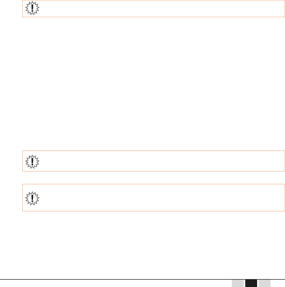
8.8.
Thissettingallowsyoutodenedierentmodesofoperationofthehornsignalaccordingtoneedsand
LEDsA,B,C,andDindicatethepatternandthesoundlevel:
Pattern Selection:Congurablefrom1to99↔LEDAindicatestensandLEDBindicatestheones.
Automatic Pattern:Thisdependsontheradiochannelused↔indicatedbyLEDD(automaticwhentheLEDis
onandmanualwhentheLEDiso).
Sound Level:Congurablefrom1to2↔indicatedbyLEDC(highiftheLEDisonandlowiftheLEDiso).
Bydefault,productsaredeliveredinautomaticpatternmodeandlevel2.
Thebuzzerisactiveaccordingtoapatterndependingonthesettingorradiochannel(automatic)ofthereceiver.
Productsmustbereadyforconguration(performstepsinChapter7.1).
1 2 3
70.ai
AUX1
AUX2
F1 F2
F3 F4
F5 F6
I
0
S
T
A
R
T
AUX2 AUX1
A
B
C
D
x1
06.ai
AUX1
AUX2
F1 F2
I
0
S
T
A
R
T
AUX2
C
D
71.ai
AUX1
AUX2
F1 F2
F3 F4
F5 F6
I
S
T
A
R
T
AUX2 AUX1
A
B
C
D
+10
-10
+1
-1
Turn ON / OFF switch to the I
(ON) position. Ensure the LEDs
AthroughDturnonandtheno.
Then press and hold the AUX2 and
F1 buttons and turn the ON / OFF
switch to START:Batteryandradio
LEDsashonceinaloop.
Release the ON / OFF button
and all other buttons to start
conguration.
LEDs indicate the existing
conguration.
To change the pattern:
• Decrement/increment the tens
with F1/F3
• Decrement/increment the ones
with F2/F4.

- 46 - Airmark - 354840C
FR
DEEN
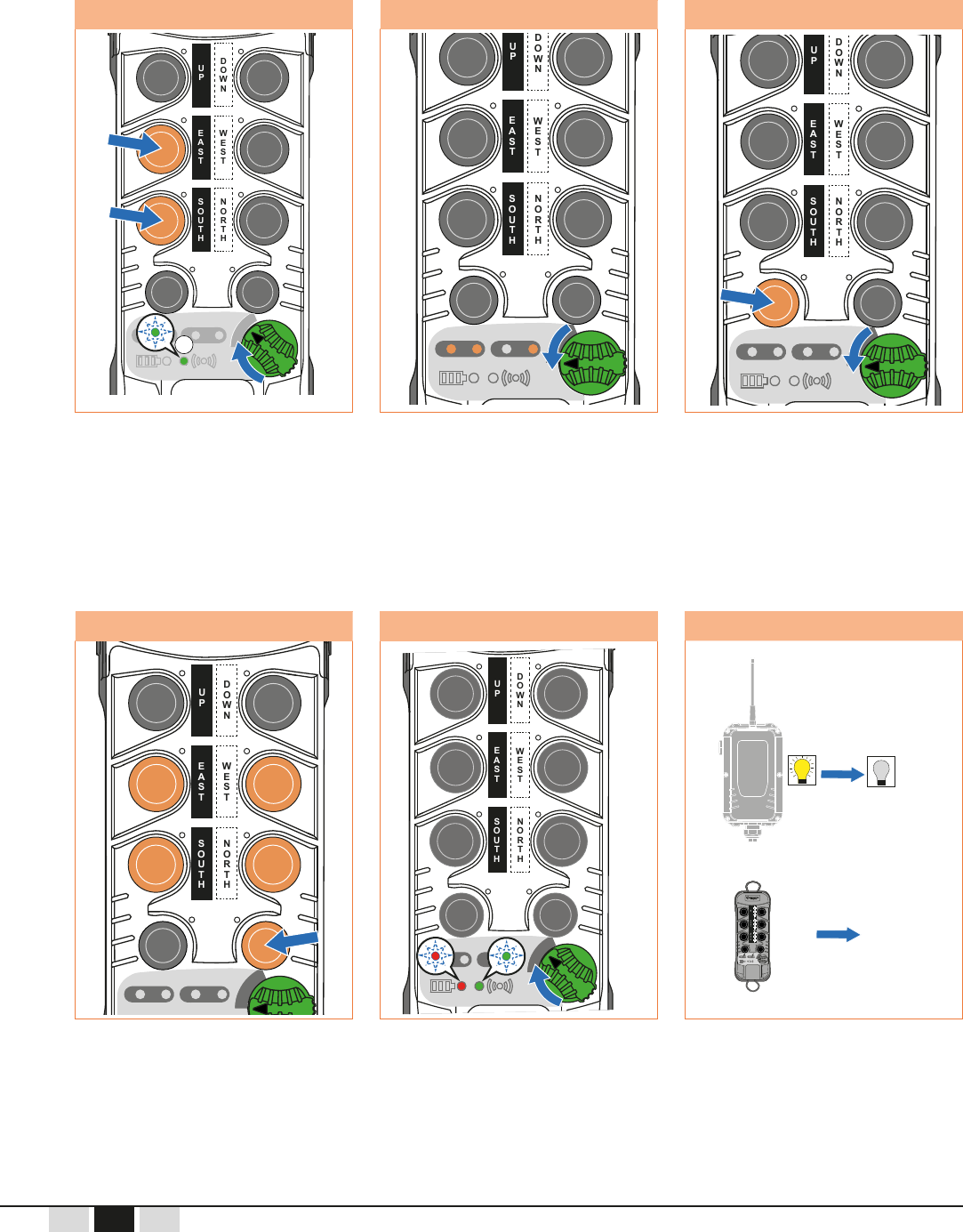
4 5 6
74.ai
AUX1
AUX2
F1 F2
F3 F4
I
0
S
T
A
R
T
AUX2 AUX1
A
B
C
D
Selectthedesiredsoundlevel
using the AUX1 button.
The AUX2 button enables
automatic mode.
Conrmthevaluebyturning
the ON / OFF switch to START.
During transmission:
• Battery andradio LEDs flash
alternately
• Receiverlightturnson.
7
61.ai
ONOFF
AUX1
AUX2
F1 F2
F3 F4
F5 F6
0
S
T
A
AUX2 AUX1
A
B
C
D
End of transmission:
• Receiverlightturnso
• Transmitter shuts down
and restarts.
72.ai
AUX1
AUX2
F1 F2
F3 F4
F5 F6
I
0
S
T
A
R
T
AUX2 AUX1
A
B
C
D
73.ai
AUX1
AUX2
F1 F2
F3 F4
F5 F6
I
0
S
T
A
R
T
AUX2 AUX1
A
B
C
D

Airmark - 354840C - 47 -
DE
FREN
8.9.
Incaseofradiointerferenceoratoofardistancebetweentheequipmentandthetransmitter,theradio
communicationmaybeinterrupted.Inthiscase,acommandtostoptheequipmentmovement(byreleasingthe
transmitterbutton)maynotbetakenintoaccount.
Toavoidrisks,themovementisstoppedwitha"passivestop"delay.Theremotecontrolhasfourpassivestop
delaysandthesettingvalueisindicatedbyLEDB:0.3sec(1ash),0.5sec(2ashes),1sec(3ashes)and
1.5sec(4ashes).
Thepassivetimemustbeproperlychosenaccordingtotheriskanalysisoftheequipmenttobecontrolled:
Iftooshort,unwantedstopsmayoccurfrequently
Iftoolong,themovementmaycontinuefortoolongandcancreatedangeroussituations.
Productsmustbereadyforconguration(ifthetransmitterandreceiverarenotpoweredonandunlocked,
perform the steps in Chapter 7.1).
1 2 3
96.ai
AUX1
AUX2
F1 F2
F3 F4
I
0
S
T
A
R
T
AUX2 AUX1
A
B
C
D
x1 x2
06.ai
AUX1
AUX2
F1 F2
I
0
S
T
A
R
T
AUX2
C
D
97.ai
AUX1
AUX2
F1 F2
F3 F4
I
0
S
T
A
R
T
AUX2 AUX1
A
B
C
D
1.5s
Turn ON / OFF switch to the I
(ON) position. Ensure the LEDs
A through D turn on and then o.
Then press and hold at the same
time AUX1, AUX2, F1 and F2
buttons and turn the ON / OFF
switch to START:
• ThebatteryLEDashesones
• TheradioLEDashes2 times.
Release the ON / OFF switch
and all other buttons to start
conguration.
Thepassivestopdelayisfactory-
setted to 0.5 sec and the LED B
ashes1time.
Press the AUX1 to scroll through
the fourpassivestopdelays: the
numberofashesontheLEDB
indicatestheselectedvalue.

- 48 - Airmark - 354840C
FR
DEEN
4 5 To abort
08.ai
AUX1
AUX2
F1 F2
F3 F4
F5 F6
I
0
S
T
A
R
T
AUX2 AUX1
A
B
C
D
61.ai
ONOFF
AUX1
AUX2
F1 F2
F3 F4
F5 F6
0
S
T
A
AUX2 AUX1
A
B
C
D
103.ai
AUX1
AUX2
F1 F2
F3 F4
F5 F6
I
0
S
T
A
R
T
AUX2 AUX1
A
B
C
D
abandon
Conrmthevaluebyturningthe
ON / OFF switch to START.
During transmission:
• Battery andradio LEDs flash
alternately
• Receiverlightturnson.
End of transmission:
• Receiverlightturnso
• Transmitter shuts down and
restarts.
Itispossibletoabortbyturningthe
ON / OFF switch from I to 0.

Airmark - 354840C - 49 -
DE
FREN
8.10. Info & Reset Menu (AUX1 + F4)
Thismenuallowsyoutorestorethefactorydefaultsandcheckthetransmitterandreceiversoftwareversions.
The reset has the following action:
Todeletepossiblesecondaryreceiverscontrolledbythetransmitter(Tandem)
Todeletealltransmitterspairedtothereceiverexceptthemainreceiverused
Torestoreallfactorydefaults(refertoChapter6.3).
Afterareset,thefactorydefaultsarerestoredandonlythetransmitterusedfortheresetisabletocommunicate
withthe"reseted"receiverandconsequentlytodrivetheequipment.
1 2 3
98.ai
AUX1
AUX2
F1 F2
F3 F4
I
0
S
T
A
R
T
AUX2 AUX1
A
B
C
D
x1 x3
99.ai
AUX1
AUX2
I
0
S
T
A
R
T
AUX2 AUX1
A
B
C
D
AUX1
AUX2
F1 F2
F3 F4
F5 F6
0
S
T
A
AUX2 AUX1
A
B
C
D
SOFTWARE
100.ai
AUX1
AUX2
I
0
S
T
A
R
T
AUX2 AUX1
A
B
C
D
SOFTWARE
Turn ON / OFF switch to the I
(ON) position. Ensure the LEDs
AthroughDturnonandtheno.
Then press and hold the AUX1
and F4 buttons and turn the
ON / OFF switch to START:
• ThebatteryLEDashesonce
• TheradioLEDashes3 times.
Release the ON / OFF switch and
all other buttons, the transmitter
softwareversionisdisplayed
(greenradioLEDiso):
• LED B indicates the hundreds
• LED C indicates the tens
• LED D indicates the units.
Todisplayreceiversoftware
versionpresstheAUX1 button:
the green radio LED turns on and
the B, C and C LEDs indicate the
versionnumber(inorderhundreds,
tens and units).
4 5
101.ai
AUX1
AUX2
F1 F2
F3 F4
F5 F6
I
0
S
T
A
R
T
AUX2 AUX1
A
B
C
D
102.ai
AUX1
AUX2
I
0
S
T
A
R
T
AUX2 AUX1
A
B
C
D
To pre-select a reset press
successivelytheF1, F2, F3, F4, F5
and F6buttons:thebatteryLED
is blinking and all others LEDs are
o.
Validatetheresetbytourningthe
ON / OFF switch to START:battery
andradioLEDsashalternatively
andthereceivermemorizethe
factorydefaults(whitelampison).

- 50 - Airmark - 354840C
FR
DEEN
To abort Rest End
103.ai
AUX1
AUX2
F1 F2
F3 F4
F5 F6
I
0
S
T
A
R
T
AUX2 AUX1
A
B
C
D
abandon
61.ai
ONOFF
AUX1
AUX2
F1 F2
F3 F4
F5 F6
0
S
T
A
AUX2 AUX1
A
B
C
D
To abort the reset, turn the
ON / OFF switch from I to 0.
At the reset end:
• Receiverwhitelampturnso
• Transmitter shuts down
and restarts.

Airmark - 354840C - 51 -
DE
FREN
9.1.
ThisfeatureswapstheselectionindicatoroftheAUX1button.
Thisfeatureisusedwhenpairedinatandembecauseeachtransmitterautomaticallyputstheprimarypaired
receiverasAandthesecondarypairedreceiverasB.Usethistoswitchnamingonanytransmittersthatdonot
match site naming for crane A and B.
SwappingcongurationisindicatedbyLEDsAandB:
• TheselectionindicatorsofreceiversAandBarenotswappedifLEDAisonandLEDBiso
• TheselectionindicatorsofreceiversAandBarenotswappedifLEDAisoandLEDBison.
Productsmustbereadyforconguration(performstepsinChapter7.1).
1 2 3
76.ai
AUX1
AUX2
F1 F2
F3 F4
F5 F6
I
0
S
T
A
R
T
AUX2 AUX1
A
B
C
D
x8x4
06.ai
AUX1
AUX2
F1 F2
I
0
S
T
A
R
T
AUX2
C
D
19.ai
AUX1
AUX2
F1 F2
F3 F4
F5 F6
I
0
S
T
A
R
T
AUX2 AUX1
A
B
C
D
Turn ON / OFF switch to the I
(ON) position. Ensure the LEDs
AthroughDturnonandtheno.
Then press and hold the AUX1 and
F5 buttons and turn the ON / OFF
switch to START:
• ThebatteryLEDturnso
• TheradioLEDashes4 times.
Release the ON / OFF switch and
all other buttons: LEDs A and
B indicate whether swapping is
enabled or disabled.
To switch from one mode to
another press the AUX1 button.
9.

- 52 - Airmark - 354840C
FR
DEEN
4 5
Bydefault,afterconguring
anAUX1functionbuttonand
after pairing,
swapping is disabled.
61.ai
ONOFF
AUX1
AUX2
F1 F2
F3 F4
F5 F6
0
S
T
A
AUX2 AUX1
A
B
C
D
Conrmthevaluebyturning
the ON / OFF to START.
During transmission:
• BatteryandradioLEDs
ashalternately
• Receiverlightturnson.
End of transmission:
• Receiverlightturnso
• Transmitter shuts down
and restarts.
77.ai
AUX1
AUX2
F1 F2
F3 F4
I
0
S
T
A
R
T
AUX2 AUX1
A
B
C
D

Airmark - 354840C - 53 -
DE
FREN
9.2. Release Function (Ungroup) (AUX1 + F3)
Thissettingallowsyoutocongurethereleaseofoneormorereceiversthatworkwiththetransmitter.
Ifautomaticreleasemodeisenabled,whenthetransmitterstopsoperating,thepairedreceiver(s)willbe
released and another transmitter can connect later.
Inthevoluntaryreleasemode,theoperatormustvoluntarilyreleaseornotthereceivers.
Productsareconguredbydefaultinautomaticreleasemode.
ReleasemodeisindicatedbythepairofAandBLEDs:
• Forautomaticrelease,LEDAisonandLEDBiso
• Forvoluntarymanualrelease,LEDAisoandLEDBison.
Productsmustbereadyforconguration(performstepsinChapter7.1).
Note: When you change this parameter, it is recommended to do the same change on both receivers. So this procedure needs to be done
with the primary Tx of each Rx.
1 2 3
87.ai
AUX1
AUX2
F1 F2
F3 F4
F5 F6
I
0
S
T
A
R
T
AUX2 AUX1
A
B
C
D
x9x9
06.ai
AUX1
AUX2
F1 F2
I
0
S
T
A
R
T
AUX2
C
D
19.ai
AUX1
AUX2
F1 F2
F3 F4
F5 F6
I
0
S
T
A
R
T
AUX2 AUX1
A
B
C
D
Turn ON / OFF switch to the I
(ON) position. Ensure the LEDs
AthroughDturnonandtheno.
Then press and hold the AUX1 and
F3 buttons and turn the ON / OFF
switch to START:
• ThebatteryLEDturnso
• TheradioLEDashes9times.
Release the ON / OFF switch and
all other buttons: LEDs A and B
indicatetheactivereleasemode
(autoorvoluntary).
To switch from one mode to
another press the AUX1 button.

- 54 - Airmark - 354840C
FR
DEEN
4 5
61.ai
ONOFF
AUX1
AUX2
F1 F2
F3 F4
F5 F6
0
S
T
A
AUX2 AUX1
A
B
C
D
Conrmthevaluebyturning
the ON / OFF switch to START.
During transmission:
• BatteryandradioLEDsash
alternately
• Receiverlightturnson.
End of transmission:
• Receiverlightturnso
• Transmitter shuts down
and restarts.
74.ai
AUX1
AUX2
F1 F2
F3 F4
I
0
S
T
A
R
T
AUX2 AUX1
A
B
C
D

Airmark - 354840C - 55 -
DE
FREN
9.3. Sign of Life Between Receivers (F1 + F5)
InTandemmodeasignoflifeisexchangedbetweenthetworeceivers.Thisfunctionisonlyvalidwhenthe
transmittercontrolsbothreceivers(A+B).
Thesignoflifedeterminesifoneofthereceivershasreleaseditssafetyrelaysorifradiocommunication
between the two is broken.
Productsareconguredatthefactoryinactivelifesignmode.
CongurationofthesignoflifemodeisindicatedbythepairofAandBLEDs:
• SignoflifeisenabledifLEDAisonandLEDBiso
• SignoflifeisdisabledifLEDAisoandLEDBison.
Ifthesignoflifedisappearsandoneofthereceivershasgonetosafety,
thesecondreceiverwillgotosafety(thisconditionisonlytrue,ifthecommunication
betweenreceiversisavailable).
Ifthesignoflifedisappearsbutthetworeceiversarestillinoperation
(safetyrelayactive),
onlythefunctionoutputrelaycommandsaredisabled.
Productsmustbereadyforconguration(ifthetransmitterandreceiverarenotpoweredonandunlocked,
perform the steps in Chapter 7.1).
1 2 3
79.ai
AUX1
AUX2
F1 F2
F3 F4
F5 F6
I
0
S
T
A
R
T
AUX2 AUX1
A
B
C
D
x1
06.ai
AUX1
AUX2
F1 F2
I
0
S
T
A
R
T
AUX2
C
D
19.ai
AUX1
AUX2
F1 F2
F3 F4
F5 F6
I
0
S
T
A
R
T
AUX2 AUX1
A
B
C
D
Turn ON / OFF switch to the I
(ON) position. Ensure the LEDs
AthroughDturnonandtheno.
Then press and hold the F1 and
F6 buttons and turn the ON / OFF
switch to START:
• ThebatteryLEDashesonce
• TheradioLEDturnso.
Release the ON / OFF switch and
all other buttons: LEDs A and B
indicate whether the sign of life is
enabled or disabled.
To switch from one status to
another, press the AUX1 button.

- 56 - Airmark - 354840C
FR
DEEN
4 5
61.ai
ONOFF
AUX1
AUX2
F1 F2
F3 F4
F5 F6
0
S
T
A
AUX2 AUX1
A
B
C
D
Conrmtheselectedstatusby
turning the ON / OFF switch to
START. During transmission:
• BatteryandradioLEDs
ashalternately
• Receiverlight turns on.
End of transmission:
• Receiverlightturnso
• Transmitter shuts down
and restarts.
77.ai
AUX1
AUX2
F1 F2
F3 F4
I
0
S
T
A
R
T
AUX2 AUX1
A
B
C
D

Airmark - 354840C - 57 -
DE
FREN
10.1. Transmitter
Dierentbuttonfunctionsareidentiedbyself-adhesivelabelstobestuckonthetransmitterboxinthespace
providedforthispurposeeachbutton.
Labelsaredeliveredinsheetstobeusedaccordingtotheapplication.
10.2. Radio Receiver Position
Thereceivershouldbemountedinaprotectedplacefromshockandweather.Theantennashouldbeasfar
awayaspossiblefromthepowercables(powersupply,motor,drive,etc.)butremaininanareafavorableto
radioreception.Itmustbelocatedwithinsightoftheoperatorhandlingtheequipment.Thereshouldbeno
metallic masses near it.
Theantennawillbelocatedhighabovetheoperatorhandlingthetransmitter.Thereshouldbenometalbetween
the operator and the antenna.
The antenna is directed towards the working areas of the transmitter (downwards in the case of a hoist).
Thecorrectorientationoftheantennaisshowninthegurebelow:
10. Installation Instructions

- 58 - Airmark - 354840C
FR
DEEN
Iftheinstallationofthereceiverdoesnotallowtheoperatortoseetheantenna,itisadvisabletoosetthe
receiverantennasunderthebeams,andpointthemverticallytowardstheradiocontrolarea,asshownbelow:
81.ai
Ifseveraldevicesareequippedwithradiocontrols,workinginthesamevicinity(e.g.,inafactory),each
transmittermustcarryclearinformationthattellstheoperatorwhichequipmentitcontrols.Similarly,theoperator
mustbeabletoidentifythecontrolscorrespondingtothedirectionsofmovementoftheequipmentbeing
steered.
10.3. Mounting the Receiver
SeeRetrievemechanicalplanforattachingthehousing.
82.ai
9.02 in
229 mm
3.54 in
90 mm
10.4. Antennas
10.4.1. Antenna Type
Thereceiverhousingisequippedwithanon-detachableantenna.However,itispossibletoinstallaremote
antenna. In this case, a BNC plug-in antenna kit must be purchased and installed (refer to Chapter 19.2
Accessories).

Airmark - 354840C - 59 -
DE
FREN
10.5. Connection
Thereceiverisequippedwithanoutputcableforconnectingthepowersupplyandrelayoutputs.
Below, the correspondence of the strand outputs and their assignments.
Function Relay Fuse Terminal
Number
Powerinput48-230Vac - FUS1 AC-1 1
Powerinput48-230Vac - - AC-2 2
Safetyrelayoutput1 K14 FUS2 RS1 3
Safetyrelayoutput2 K16 - RS2 4
FunctionONoutputrelay K13 - RM 5
ONrelayoutput K13 - RM 6
AUXandselection
relaycommon
- FUS3 COM1 7
Functionrelayoutput K10 - Aux 1 8
FunctionrelayoutputAux1 K11 - Aux 2-1 9
FunctionrelayoutputAux2 K12 - Aux 2-2 10
Common 2 - FUS4 COM2 11
FunctionrelayoutputF1 K1 - F1.1 12
FunctionrelayoutputF2 K2 - F2.1 13
FunctionrelayoutputF1/F2 K3 - F1.2/F2.2 14
Common 3 - FUS5 COM3 15
FunctionrelayoutputF3 K4 - F3.1 16
FunctionrelayoutputF4 K5 - F4.1 17
FunctionrelayoutputF3/F4 K6 - F3.2/F4.2 18
Common 4 - FUS6 COM4 19
FunctionrelayoutputF5 K7 - F5.1 20
FunctionrelayoutputF6 K8 - F6.1 21
FunctionrelayoutputF5/F6 K9 - F5.2/F6.2 22
WireDiagram.ai
Wire diagram
Power supply
48-230Vac
To
12Vdc
Fuse 1
1
2
Power
AC- 1
AC- 2
Fuse 2
3
4
K16
K14
5
6
K13
Main / Start
Stop in
Stop out
Start in
Start out
Fuse 3
8
7
K10
9
K11
10
K12
Fuon Aux
Aux 1
Aux 2-1
Aux 2-2
COM1
Raux
Rsel1
Rsel2
Fuse 4
12
11
K1
13
K2
14
K3
Push buon 1-2
F1.1
F2.1
F1.2/F2.2
COM2
SOUTH
NORTH
SOUTH/
NORTH
Fuse 5
16
15
K4
17
K5
18
K6
Push buon 3-4
F3.1
F4.1
F3.2/F4.2
COM3
EAST
WEST
EAST/
WEST
Fuse 6
20
19
K7
21
K8
22
K9
Push buon 5-6
F5.2/F6.2
F5.1
F6.1
COM4
UP
DOWN
UP/
DOWN

- 60 - Airmark - 354840C
FR
DEEN
11.1. Receiver Maintenance
Thehousingcanonlybedisassembledbytrainedpersonnelina“controlled”environment.
Partscanonlybereplacedwithidenticalspareparts.
Checktheconnectionoftheantenna;itmustbecleanandunoxidized.
Checkthequalityofpowersupplyandcontroloutputwiring.
Correctoperationofshutdowncircuits,active.
Conditionofcovergasket,tightnessoffasteningscrews.
Useonlynon-aggressivesoap-basedcleaners.
11.2. Transmitter Maintenance
The transmitter housing must not be opened.
Regularlycheck the condition ofthe transmitter,payingparticular attentionto the batteriesin the battery
compartment.Ifthetransmitterisnotusedforalongperiodoftime,itisrecommendedtoremovethebatteries.
Ifanyofthefunctionbuttonmembranesorthetransmitterhousinggasketaredamaged,theequipmentshould
not be used until these sealing parts are replaced.
Otherwise,anyliquid,dust,orforeignobjectmaydamagethetransmitter.
Theuser'sattentionisdrawntotherisksofusingtheremotecontrolinanenvironmentcontainingpolymer
solventsorgluesthatcoulddegradetheproperfunctioningofthetransmitter'smechanicalparts.
Cleanthetransmitterbyremovinganyadheringforeignmatter.
Useonlynon-aggressivesoap-basedcleaners.
11. Maintenance

Airmark - 354840C - 61 -
DE
FREN
Allourdevicesareguaranteedfortwoyearsfromthedayofshipment.
Repairs,modicationsorthereplacementofadeviceduringthewarrantyperiodshallnotextendthe
warrantyperiod.
Restriction:
Thewarrantydoesnotcoverdefectsresultingfrom:
Transport
Incorrect operation or failure to follow the connection diagrams during start up
Lackofmonitoringormaintenance,usenotinaccordancewiththespecicationsinthetechnicalmanualand,
ingeneral,storage,operatingorenvironmentalconditions(atmospheric,chemical,electrical,mechanicalorother
inuences)whicharenotsuitableornotforeseenatthetimeoforder
Thewarrantycannotbeexercisedifmodications,dismantlingoradditionshavebeenmadebythecustomer
withoutthewrittenconsentofourCompany.
TheresponsibilityofConductix-Wamperduringtheperiodofwarrantyislimitedtoanymaterialorconstruction
defect;thisincludestherepairinitsworkshopsorthefreereplacementofpartsrecognizedasdefective
accordingtheexpertiseofits“technicalservices”.Conductix-Wampercannotgiverighttoanycompensationfor
damages.
Intheeventofadisputeconcerningsupplyorpayment,THECOMMERCIALCOURTOFGRENOBLEisthe
onlycompetentauthority,evenintheeventofAppealorofpluralityofdefendants.
12. Warranty

- 62 - Airmark - 354840C
FR
DEEN
13.1. Receiver
Housing Material PA66GF30(PCcover)
Housing color Blackbackgroundandtranslucent/transparentcover
Protection Index IP65(Indooruseonly)
Mass 1.4kg (including cable)
12.20 (without antenna, with PES) x 5.90 (with horn) x 3.14 in
310 (without antenna, with PES) x 150 (with horn) x 80 mm
Fastening 4x screws M3 – 229 x 90mm
Possibilitytoaddmagnetswithorwithoutsilentblocks
Operating Temperature -20°Cto+55°C
Storage Temperature -20°Cto+70°C
Connection 22-strandscable,section0.75mm²,AWG18
(0.8mm²Kcmil)
Length 59 in / 1.5 m
Cable Entry PE M32 diam 17-25
Power Indicator Light Amber LED
Radio Indicator Light Green LED
Safety relay active indicator light Red LED
Function indicator light Whitelamp
Sound indicator Horn95dB
Antenna Wireantennaprotectedbycableglandandplastictube
Breathable membrane (internal anti-condensation) Yes, Goretex
Pollution degree 2
13.

Airmark - 354840C - 63 -
DE
FREN
Power Supply
Supply voltage (steady state) 48Vacto230Vac±10%-50/60Hz
Protection Fuse 0.5 A
Consumption <15W
Pollution degree 2
Overvoltage category III(MKR)
Safety relay outputs
Number of outputs (2 relays in series) 2
Contacts AgNi+Au
Contact Type Guidedcontactrelays
Break Capacity 250Vac@5Amax(atmaxoperatingtemperature)
12Vdc@50mAmin
Max Power at cos ø = 1 2000VA
100,000(230Vac,6A,cosphi=1)
Protection Fuse 5 A (cartridge 0.2 x 0.79 in / 5 x 20 mm)
Control relay outputs
Number of outputs 16(3x3movement+3AUX+1ON)
Contacts AgNi+Au
Contact Type Contactrelays
Break Capacity 250Vac@5Amax(atmaxoperatingtemperature)
12Vdc@50mAmin
Max Power at cos ø = 1 2000VA
100,000(230Vac,6A,cosphi=1)
Protection 4 x Fuse 5A (cartridge 0.2 x 0.79 in / 5 x 20 mm)
13.1.1.
75.ai
12.20 in
310 mm
5.90 in
150 mm
3.14 in
80 mm

- 64 - Airmark - 354840C
FR
DEEN
13.2. Transmitter
Housing Material PA66 GF 30
Housing color Orange RAL2004
Protection Index IP65
Mass 300g max
7.09 x 2.76 x 1.77 in
180 x 70 x 45 mm
Operating Temperature -20°Cto+50°C
Storage Temperature -30°Cto+70°C
Transport 2 strap anchor points
Protection Foam,protectivecover
Breathable membrane (internal anti-condensation) Yes
Pollution degree 2
Overvoltage category I(MKT)
Power Supply Battery
Pollution degree 2
Overvoltage category I
Number of function buttons 6
Number of AUX buttons 2
Battery life 100 h
Power Indicator Light Red
Radio Indicator Light Green
Orange
Orange
13.2.1.
80.ai
7.09 in
180 mm
1.77 in
45 mm
2.76 in
70 mm

Airmark - 354840C - 65 -
DE
FREN
13.3. Radio
Transmission Frequency 433-440MHz
Number of Channels 92
Space Between Channels 75kHz
Receiver Sensitivity -100dBm
Transmission Power 1mW
Modulation FSK
Frame Hamming4distancewithencryptionagainst
external attacks
Medium Range* 54.7-109.4yd/50-100minindustrialsetting*
437.6ydin/400minopenspace
Antenna Output Impedance 50 Ohms
Response Time at Startup 500 ms
Command Response Time 300 ms
* The range varies according to the environmental conditions of the transmitter and receiving antenna (frames, metal walls, etc.).
13.4. Battery
Type Alkaline Nickel-Metal-Hydride
Format LR6 (AA) AA-NIMH
Voltage 1.5V 1.35V
Operating Temperature 0°Cto+50°C 0°Cto+40°C
Storage Temperature -20°Cto+70°C -10°Cto+60°C

- 66 - Airmark - 354840C
FR
DEEN
ProductscomplywiththerequirementsoftheFederalCommunicationsCommission
Section 15.231 (b)(2) Periodic operation in the band 40.66-40.70 MHz and above 70 MHz.
14.1. FCC (Federal Communications Commission) Regulations
AnychangesormodicationstothisequipmentnotexpresslyapprovedbyJAYElectroniquecouldresultincause
harmfulinterferenceandvoidtheFCCauthorizationtooperatethisequipment.
ThisequipmenthasbeentestedandfoundtocomplywiththelimitsforaClassAdigitaldevice,pursuanttothe
FCC Part 15.
Theselimitsaredesignedtoprovidereasonableprotectionagainstharmfulinterferencewhentheequipment
isoperatedinacommercialenvironment.
Thisequipmentgenerates,uses,andcanradiateradiofrequencyenergyand,ifnotinstalledandusedin
accordancewiththeinstructionmanual,maycauseharmfulinterferencetoradiocommunications.
Operationofthisequipmentinaresidentialareaislikelytocauseharmfulinterferenceinwhichcasetheuser
willberequiredtocorrecttheinterferenceattheirownexpense.
ThisportableequipmentanditsantennascomplywithFCCradiationexposurelimitssetforthforanuncontrolled
environment.
To maintain compliance, follow the instructions below:
1.Thistransmittermustnotbeco-locatedoroperatedinconjunctionwithanyotherantennaortransmitter.
2.Avoiddirectcontactwiththeantennaorkeepcontacttoaminimumwhenusingthisequipment.
Authorized Antennas:see“Antennas”chapter
Antenna Installation Requirements:SeeChapter“ReceiverInstallation”
:
FCCID:OQMKTTransmitter
FCCID:OQMKRReceiver
IC (Industry Canada) Regulation
ThisClass(A)digitalapparatusmeetsalltherequirementsoftheCanadianNMB-003standard.
ThisportableequipmentanditsantennascomplywithCNR102radiationexposurelimitsapplicablefor
anuncontrolledenvironment.Tomaintaincompliance,followtheinstructionsbelow:
1.Thistransmittermustnotbeco-locatedoroperatedinconjunctionwithanyotherantennaortransmitter.
2.Avoiddirectcontactwiththeantennaorkeepcontacttoaminimumwhenusingthisequipment.
Thisradiotransmitter(ICtransmitter:3393A-KT,ICreceiver:3393A-KRdependingonthemodel)hasbeen
approvedbyIndustryCanadaforusewiththeantennatypeslistedintheSection“Antennas”.Thisistheonly
waytoensurethattheantennawillbeabletooperatewiththesamemaximumallowablegainandimpedance
foreachtypeofantennalisted.Antennatypesnotincludedinthislist,andwhosegainisgreaterthanthe
maximumgainlisted,arestrictlyprohibitedforusewiththetransmitter.
Authorized Antennas:see“Antennas”chapter
Antenna Installation Requirements:SeeChapter“ReceiverInstallation”
ThisdevicecomplieswithIndustryCanada’sRSSforlicense-exemptradioequipment.
Operation is permitted under the following two conditions:
1.Thedevicemustnotcauseinterference
2.Theuserofthisequipmentmustacceptanyradiointerferencereceived,eveniftheinterferenceislikely
toaecttheoperationoftheequipment
Product IC:
ICtransmitter:3393A-KT
ICreceiver:3393A-KR
Transmitter RF Exposure
ThisdevicecomplieswiththeRFpersonalexposurerequirementlimitlevelsdenedbyISDE.Theunitshould
notbeinstalledincloseproximitytoorusedinconjunctionwithanyotherantennaortransmitter.
14. FCC (Federal Communications Commission) Regulations

Airmark - 354840C - 67 -
DE
FREN
14. Réglementation FCC
(Commission fédéral des communications)
Lesproduitssontconformesaveclesexigencesdelacommissionfédéraldescommunications
.
14.1. Réglementation FCC (Commission fédéral des communications)
ToutesmodicationsapportéesàcetéquipementnonexpressémentapprouvéesparJAYElectroniquepeuvent
causerdesinterférencesnuisiblesetannulerl'autorisationFCCd'utilisercetéquipement.
Cetéquipementaététestéetdéclaréconformeauxlimitesd’unappareilnumériquedeclasseA,conformément
àlaFCCpart15.
Ceslimitessontconçuespourfourniruneprotectionraisonnablecontrelesinterférencesnuisibleslorsque
l’équipementestutilisédansunenvironnementcommercial.
Cetéquipementgénère,utiliseetpeutémettredel’énergieradiofréquenceet,s’iln’estpasinstalléetutilisé
conformémentaumanueld’instruction,peutprovoquerdesinterférencesnuisiblesauxcommunicationsradio.
Lefonctionnementdecetéquipementdansunezonerésidentielleestsusceptibledeprovoquerdes
interférencesnuisibles,auquelcasl’utilisateurdevracorrigerlesinterférencesàsespropresfrais.
Cetéquipementportableavecsesantennesestconformeauxlimitesd’expositionauxrayonnementsdelaFCC
déniespourunenvironnementnoncontrôlé.
Pourmaintenirlaconformité,suivezlesinstructionsci-dessous:
1.Cetémetteurnedoitpasêtreco-localiséoufonctionnerenconjonctionavectouteautreantenneouémetteur.
2.Eviteztoutcontactdirectavecl’antenneougardezlecontactauminimumpendantl’utilisationdecetéquipement.
Antennes autorisées :voirchapitre«Antennes»
Exigences d’installation des antennes :voirchapitre«InstallationduRécepteur»
:
FCCID:ÉmetteurOQMKT
FCCID:RécepteurOQMKR
Réglementation IC (Industrie Canada)
Cetappareilnumériquedelaclasse(A)respectetouteslesexigencesdelanormeNMB-003duCanada.
Cetéquipementportableavecsesantennesestconformeauxlimitesd’expositionauxrayonnementsdela
CNR102applicablespourunenvironnementnoncontrôlé.Pourmaintenirlaconformité,suivezlesinstructions
ci-dessous :
1.Cetémetteurnedoitpasêtreco-localiséoufonctionnerenconjonctionavectouteautreantenneouémetteur.
2.Eviteztoutcontactdirectavecl’antenneougardezlecontactauminimumpendantl’utilisationdecetéquipement.
Leprésentémetteurradio(ICémetteur:3393A-KT,ICrécepteur:3393A-KRenfonctiondumodèle)aété
approuvéparIndustrieCanadapourfonctionneraveclestypesd’antenneénumérésdanslechapitre«Antennes
»ayantungainadmissiblemaximalautoriséetuneimpédanceidentiquepourchaquetyped’antenneindiqué.
Lestypesd’antennenoninclusdanscetteliste,etdontlegainestsupérieuraugainmaximalindiqué,sont
strictementinterditspourl’utilisationavecl’émetteur.
Antennes autorisées :voirchapitre«Antennes»
Exigences d’installation des antennes :voirchapitre«InstallationduRécepteur»
LeprésentappareilestconformeauxCNRd'IndustrieCanadaapplicablesauxappareilsradioexemptsde
licence.
L'exploitationestautoriséeauxdeuxconditionssuivantes:
1.L’appareilnedoitpasproduiredebrouillage;
2.l'utilisateurdel'appareildoitacceptertoutbrouillageradioélectriquesubi,mêmesilebrouillageestsusceptible
d'encompromettrelefonctionnement.
IC du produit :
ICémetteur:3393A-KT
ICrécepteur:3393A-KR
Leprésentappareilestconformeauxniveauxlimitesd’exigencesd’expositionRFauxpersonnesdéniespar
ISDE.L’appareilnedoitpasêtreinstalléàproximitéouêtreutiliséenconjonctionavecuneautreantenneouun
autreémetteur.

- 68 - Airmark - 354840C
FR
DEEN
According to the standard:
Safetyrequirementsforelectricalequipmentformeasurement,control,andlaboratoryuse;
• IEC 61010-1:2010/AMD1 :2016
• UL 61010-1:2012/R :2019-07
• CSA C22.2 No. 61010-1:2012/A1 :2018-11
Degreesofprotectionprovidedbyenclosures(IPcode):
• IEC 60529:1989/A1:1999
Altitude of the site of installation does not exceed 2000 m.
Therelativehumidityoftheairdoesnotexceed50%atamaximumtemperatureof+40°C.
Higherrelativehumiditiesmaybepermittedatlowertemperatures,e.g.90%at+20°C.
15.
16. Recycling and Waste Management
Recyclage_Logo_poubelle.ai
Whenthisdeviceisworn,itshouldnotbedisposedofinanykindof
dumping ground.
Itcanbetakentothespeciccollectioncenters,dierentiatedbylocal
administrations, or to the distributors who take care of them.
Thesortingofelectronicwasteavoidspossiblenegativeconsequences
ontheenvironment,derivedfromaninappropriateeliminationandallows
theprocessingandrecyclingofitsmaterials,whichfavorsimportantsavings
intermsofenergyandresources.
17. Manufacturer Information
Manufacturer and Factory:
Jayélectronique
ZAC la Bâtie, rue Champrond
F38334 SAINT ISMIER Cedex
Tel: + 33 (0)4 76 41 44 00
ww.jay-electronique.com
18. Compliance Statement
Productconformitystatementsareavailableatwww.jay-electronique.com

Airmark - 354840C - 69 -
DE
FREN
19. Appendix
19.1. Radio Frequency Table
channel1433.1MHz channel32435.425MHz channel63437.75MHz
channel2433.175MHz channel33435.5MHz channel64437.825MHz
channel3433.25MHz channel34435.575MHz channel65437.9MHz
channel4433.325MHz channel35435.65MHz channel66437.975MHz
channel5433.4MHz channel36435.725MHz channel67438.05MHz
channel6433.475MHz channel37435.8MHz channel68438.125MHz
channel7433.55MHz channel38435.875MHz channel69438.2MHz
channel8433.625MHz channel39435.95MHz channel70438.275MHz
channel9433.7MHz channel40436.025MHz channel71438.35MHz
channel10433.775MHz channel41436.1MHz channel72438.425MHz
channel11433.85MHz channel42436.175MHz channel73438.5MHz
channel12433.925MHz channel43436.25MHz channel74438.575MHz
channel13434MHz channel44436.325MHz channel75438.65MHz
channel14434.075MHz channel45436.4MHz channel76438.725MHz
channel15434.15MHz channel46436.475MHz channel77438.8MHz
channel16434.225MHz channel47436.55MHz channel78438.875MHz
channel17434.3MHz channel48436.625MHz channel79438.95MHz
channel18434.375MHz channel49436.7MHz channel80439.025MHz
channel19434.45MHz channel50436.775MHz channel81439.1MHz
channel20434.525MHz channel51436.85MHz channel82439.175MHz
channel21434.6MHz channel52436.925MHz channel83439.25MHz
channel22434.675MHz channel53437MHz channel84439.325MHz
channel23434.75MHz channel54437.075MHz channel85439.4MHz
channel24434.825MHz channel55437.15MHz channel86439.475MHz
channel25434.9MHz channel56437.225MHz channel87439.55MHz
channel26434.975MHz channel57437.3MHz channel88439.625MHz
channel27435.05MHz channel58437.375MHz channel89439.7MHz
channel28435.125MHz channel59437.45MHz channel90439.775MHz
channel29435.2MHz channel60437.525MHz channel91439.85MHz
channel30435.275MHz channel61437.6MHz channel92439.925MHz
channel31435.35MHz channel62437.675MHz

- 70 - Airmark - 354840C
FR
DEEN
19.2. Accessories
19.2.1. US Version
OWE20 Neck strap included with each transmitter
PWM111Handstrap
Receivermagneticmountingkit
UWE102 Shoulder strap
PWM113 Transmitter magnetic mount
UWE106 Transmitter belt clip
UWE320Transmitterprotectivecover
PWM107Transmitterbeltcarryingsleeve
19.2.2. External antenna option
Theantennaofthereceiverproductissimplewireinstandardversion.Itispossibletochangethis
antennabylistedantennasbelowwithanadaptorinoption:
• VUA110AH (with 10m cable)
Type:throughinsulatedremote,1/2wave,BNCconnection
Approximate length: 320 mm
Requireddrillhole:15mm
• VUA103AM (with 3m cable)
• VUA105AM (with 5m cable)
Type:insulatedmagneticremote,tuned,BNCconnection
Approximate length: 440 mm
• OWR02
MMCx - BNC adapter, 10cm, to connect an additionnal antenna

