
LAB MANUAL
CS8582 - OBJECT ORIENTED ANALYSIS AND DESIGN LABORATORY
Regulation 2017
Year / Semester: III / V
Aug 2020–Dec 2020
222020202019
ST. ANNE’S
COLLEGE OF ENGINEERING AND TECHNOLOGY
ANGUCHETTYPALAYAM, PANRUTI – 607 110
DEPARTMENT OF COMPUTER SCIENCE AND ENGINEERING
PREPARED BY
Mrs. Z.Asmathunnisa, M.Tech.,
Assistant Professor /CSE

CS8582 - OBJECT ORIENTED ANALYSIS AND DESIGN LABORATORY
OBJECTIVES:
• To capture the requirements specification for an intended software system
• To draw the UML diagrams for the given specification
• To map the design properly to code
• To test the software system thoroughly for all scenarios
• To improve the design by applying appropriate design patterns.
Draw standard UML diagrams using an UML modeling tool for a given case study and
map design to code and implement a 3 layered architecture. Test the developed code and
validate whether the SRS is satisfied.
1. Identify a software system that needs to be developed.
2. Document the Software Requirements Specification (SRS) for the identified system.
3. Identify use cases and develop the Use Case model.
4. Identify the conceptual classes and develop a Domain Model and also derive a Class
Diagram from that.
5. Using the identified scenarios, find the interaction between objects and represent them
using
UML Sequence and Collaboration Diagrams
6. Draw relevant State Chart and Activity Diagrams for the same system.
7. Implement the system as per the detailed design
8. Test the software system for all the scenarios identified as per the usecase diagram
9. Improve the reusability and maintainability of the software system by applying
appropriate design patterns.
10. Implement the modified system and test it for various scenarios
SUGGESTED DOMAINS FOR MINI-PROJECT:
1.
Passport automation system.
2.
Book bank
3.
Exam registration
4.
Stock maintenance system.
5.
Online course reservation system
6.
Airline/Railway reservation system
7.
Software personnel management system
8.
Credit card processing
9.
e-book management system
10.
Recruitment system
11.
Foreign trading system
12.
Conference management system
13.
BPO management system
14.
Library management system
15.
Student information system

TABLE OF CONTENTS
S.NO.
DATE
EXPERIMENT TITLE
MARKS/10
SIGN.
1
Case Tools
2
Passport automation system
3
Book bank
4
Exam Registration
5
Stock maintenance system
6
Online course reservation system
7
Airline/Railway reservation system
8
Software personnel management system
9
Credit card processing
10
E-book management system
11
Recruitment system
12
Foreign trading system
13
Conference Management System
14
BPO Management System
15
Library management system
16
Student information system

Ex. No.: 1
Date:
INTRODUCTION:
CASE TOOLS
CASE tools known as Computer-aided software engineering tools is a
kind of component-based development which allows its users to rapidly
develop information systems. The main goal of case technology is the
automation of the entire information systems development life cycle process
using a set of integrated software tools, such as modeling, methodology and
automatic code generation. Component based manufacturing has several
advantages over custom development. The main advantages are the
availability of high quality, defect free products at low cost and at a faster
time. The prefabricated components are customized as per the requirements
of the customers. The components used are pre-built, ready-tested and add
value and differentiation by rapid customization to the targeted customers.
However the products we get from case tools are only a skeleton of the final
product required and a lot of programming must be done by hand to get a
fully finished, good product.
CHARACTERISTICS OF CASE:
Some of the characteristics of case tools that make it better than
customized development are;
❖ It is a graphic oriented tool.
❖ It supports decomposition of process.
Some typical CASE tools are:
❖ Unified Modeling Language
❖ Data modeling tools, and
❖ Source code generation tools
INTRODUCTION TO UML (UNIFIED MODELING LANGUAGE):
The UML is a language for specifying, constructing, visualizing, and
documenting the software system and its components. The UML is a
graphical language with sets of rules and semantics. The rules and semantics
of a model are expressed in English in a form known as OCL (Object
Constraint Language). OCL uses simple logic for specifying the properties

of a system. The UML is not intended to be a visual programming language.
However it has a much closer mapping to object-oriented programming
languages, so that the best of both can be obtained. The UML is much
simpler than other methods preceding it. UML is appropriate for modeling
systems, ranging from enterprise information system to distributed web
based application and even to real time embedded system. It is a very
expensive language addressing all views needed to develop and then to
display system even though understand to use. Learning to apply UML
effectively starts forming a conceptual mode of languages which requires
learning.
Three major language elements:
❖ UML basic building blocks
❖ Rules that dictate how this building blocks put together
❖ Some common mechanism that apply throughout the language
The primary goals in the design of UML are:
1. Provides users ready to use, expressive visual modeling
language as well so they can develop and exchange
meaningful models.
2. Provide extensibility and specialization mechanisms to
extend the core concepts.
3. Be independent of particular programming languages and
development processes.
4. Provide formal basis for understanding the modeling
language.
5. Encourage the growth of the OO tools market.
6. Support higher-level development concepts.
7. Integrate best practices and methodologies.
Every complex system is best approached through a small set of
nearly independent views of a model. Every model can be expressed at
different levels of fidelity. The best models are connected to reality. The
UML defines nine graphical diagrams:
1. Class diagram
2. Use-case diagram
3. Behavior diagram
3.1. Interaction diagram
3.1.1. sequence diagram
3.1.2. collaboration diagram
3.2. state chart diagram
3.3. activity diagram

4. Implementation diagram
4.1component diagram
4.2deployment diagram
1. UML class diagram:
The UML class diagram is also known as object modeling. It is a
static analysis diagram. These diagrams show the static structure of the
model. A class diagram is a connection of static model elements, such as
classes and their relationships, connected as a graph to each other and to
their contents.
2. Use-case diagram:
The functionality of a system can be described in a number of
different use-cases, each of which represents a specific flow of events in a
system. It is a graph of actors, a set of use-cases enclosed in a boundary,
communication, associations between the actors and the use-cases, and
generalization among the use-cases.
3. Behavior diagram:
It is a dynamic model unlike all the others mentioned before. The
objects of an object oriented system are not static and are not easily
understood by static diagrams. The behavior of the class’s instance (an
object) is represented in this diagram. Every use-case of the system has an
associated behavior diagram that indicates the behavior of the object. In
conjunction with the use-case diagram we may provide a script or interaction
diagram to show a time line of events. It consists of sequence and
collaboration diagrams.
4. Interaction diagram
It is the combination of sequence and collaboration diagram. It is used
to depict the flow of events in the system over a timeline. The interaction
diagram is a dynamic model which shows how the system behaves during
dynamic execution.
5. State chart diagram:
It consists of state, events and activities. State diagrams are a familiar
technique to describe the behavior of a system. They describe all of the

possible states that a particular object can get into and how the object's state
changes as a result of events that reach the object. In most OO techniques,
state diagrams are drawn for a single class to show the lifetime behavior of a
single object.
6. Activity diagram:
It shows organization and their dependence among the set of
components. These diagrams are particularly useful in connection with
workflow and in describing behavior that has a lot of parallel processing. An
activity is a state of doing something: either a real-world process, or the
execution of a software routine.
7. Implementation diagram:
It shows the implementation phase of the systems development, such
as the source code structure and the run-time implementation structure.
These are relatively simple high level diagrams compared to the others seen
so far. They are of two sub-diagrams, the component diagram and the
deployment diagram.
8. Component diagram:
These are organizational parts of a UML model. These are boxes to
which a model can be decomposed. They show the structure of the code
itself. They model the physical components such as source code, user
interface in a design. It is similar to the concept of packages.
9. Deployment diagram:
The deployment diagram shows the structure of the runtime system. It
shows the configuration of runtime processing elements and the software
components that live in them. They are usually used in conjunction with
deployment diagrams to show how physical modules of code are distributed
on the system.
NOTATION ELEMENTS:
These are explanatory parts of UML model. They are boxes which
may apply to describe and remark about any element in the model. They

provide the information for understanding the necessary details of the
diagrams.
Relations in the UML:
are:
These are four kinds of relationships used in an UML diagram, they
❖ Dependency
❖ Association
❖ Generalization
❖ Realization
Dependency:
It is a semantic relationship between two things in which a change one
thing affects the semantics of other things. Graphically a dependency is
represented by a non-continuous line.
Association:
It is a structural relationship that describes asset of links. A link is
being connected among objects. Graphically association is represented as a
solid line possibly including label.
Generalization:
It is a specialized relationship in which the specialized elements are
substitutable for object of the generalized element. Graphically it is a solid
line with hollow arrow head parent.
Realization:
It is a semantic relation between classifiers. Graphically it is
represented as a cross between generalization and dependency relationship.
Where UML can be used:
UML is not limited to modeling software. In fact it is expressive to
model non-software such as to show in structure and behavior of health case
system and to design the hardware of the system.

Conceptual model be UML:
UML you need to form the conceptual model of UML. This requires
three major elements:
❖ UML basic building blocks.
❖ Rules that dictate how this building blocks are put
together.
❖ Some common mechanism that apply throughout the
language.
Once you have grasped these ideas, you may be able to read. UML
create some basic ones. As you gain more experience in applying conceptual
model using more advanced features of this language.
Building blocks of the UML:
The vocabulary of UML encompasses these kinds of building blocks.
Use CASE definition:
Description:
A use case is a set of scenarios tied together by a common user goal.
A use case is a behavioral diagram that shows a set of use case actions and
their relationships.
Purpose:
The purpose of use case is login and exchange messages between
sender and receiver (Email client).
Main flow:
First, the sender gives his id and enters his login. Now, he enters the
message to the receiver id.
Alternate flow:
If the username and id by the sender or receiver is not valid, the
administrator will not allow entering and “Invalid password” message is
displayed.

Pre-condition:
A person has to register himself to obtain a login ID.
Post-condition:
The user is not allowed to enter if the password or user name is not
valid.
Class diagram:
Description:
❖ A class diagram describes the type of objects in system and
various kinds of relationships that exists among them.
❖ Class diagrams and collaboration diagrams are alternate
representations of object models.
During analysis, we use class diagram to show roles and
responsibilities of entities that provide email client system behaviors design.
We use to capture the structure of classes that form the email client system
architecture.
A class diagram is represented as:
<<Class name>>
<<Attribute 1>>
<<Attribute n>>
<<Operation ()>>
Relationship used:
A change in one element affects the other
Generalization:
It is a kind of relationship
State chart:

Description:
❖ The state chart diagram made the dynamic behavior of individual
classes.
❖ State chart shows the sequences of states that an object goes through
events and state transitions.
❖ A state chart contains one state ‘start’ and multiple ‘end’ states.
The important objectives are:
Decision:
It represents a specific location state chart diagram where the work
flow may branch based upon guard conditions.
Synchronization:
It gives a simultaneous workflow in a state chart diagram. They
visually define forks and joints representing parallel workflow.
Forks and joins:
❖ A fork construct is used to model a single flow of control.
❖ Every work must be followed by a corresponding join.
❖ Joints have two or more flow that unit into a single flow.
State:
A state is a condition or situation during a life of an object in which it
satisfies condition or waits for some events.
Transition:
It is a relationship between two activities and between states and
activities.
Start state:
A start state shows the beginning of a workflow or beginning of a
state machine on a state chart diagram.
End state:

It is a final or terminal state.
Activity diagram
Description:
Activity diagram provides a way to model the workflow of a
development process. We can also model this code specific information
such as class operation using activity diagram. Activity diagrams can model
different types of diagrams. There are various tools involved in the activity
diagram.
Activity:
An activity represents the performance of a task on duty. It may also
represent the execution of a statement in a procedure.
Decision:
A decision represents a condition on situation during the life of an
object, which it satisfies some condition or waits for an event.
Start state:
It represents the condition explicitly the beginning of a workflow on
an activity.
Object flow:
An object on an activity diagram represents the relationship between
activity and object that creates or uses it.
Synchronization:
It enables us to see a simultaneous workflow in an activity.
End state:
An end state represents a final or terminal state on an activity diagram
or state chart diagram.

Sequence diagram:
Description:
A sequence diagram is a graphical view of scenario that shows object
interaction in a time based sequence what happens first what happens next.
Sequence diagrams are closely related to collaboration diagram.
The main difference between sequence and collaboration diagram is
that sequence diagram show time based interaction while collaboration
diagram shows objects associated with each other.
The sequence diagram for the e-mail client system consists of the
following objectives:
Object:
An object has state, behavior and identity. An object is not based is
referred to as an instance.
The various objects in e-mail client system are:
❖ User
❖ Website
❖ Login
❖ Groups
Message icon:
A message icon represents the communication between objects
indicating that an action will follow. The message icon is the horizontal
solid arrow connecting lifelines together.
Collaboration diagram:
Description:
Collaboration diagram and sequence diagrams are alternate
representations of an interaction. A collaboration diagram is an interaction
diagram that shows the order of messages that implement an operation or a
transaction. Collaboration diagram is an interaction diagram that shows the
order of messages that implement an operation or a transaction.

Collaboration diagram shows object s, their links and their messages. They
can also contain simple class instances and class utility instances.
During, analysis indicates the semantics of the primary and secondary
interactions. Design, shows the semantics of mechanisms in the logical
design of system.
Toggling between the sequence and collaboration diagrams
When we work in either a sequence or collaboration diagram, it is
possible to view the corresponding diagram by pressing F5 key.
CONCLUSION:
Thus the study for case tools was done.

Ex no:2
Date:
PASSPORT AUTOMATION SYSTEM
AIM:
To create an automated system to perform the Passport Process.
(I) PROBLEM STATEMENT:
Passport Automation System is used in the effective dispatch of
passport to all of the applicants. This system adopts a comprehensive
approach to minimize the manual work and schedule resources, time in a
cogent manner. The core of the system is to get the online registration form
(with details such as name, address etc.,) filled by the applicant whose
testament is verified for its genuineness by the Passport Automation System
with respect to the already existing information in the database.
( II )SOFTWARE REQUIREMENT SPECIFICATION:
2.1SOFTWARE INTERFACE
• Front End Client - The applicant and Administrator online
interface is built using
JSP and HTML. The Administrators's local interface is built using
Java.
• Web Server - Glassfish application server(Oracle Corporation).
• Back End - Oracle database.
2.2HARDWARE INTERFACE
The server is directly connected to the client systems. The client
systems have access to the database in the server.

registration
enter applicant id
check status
administrator
applicant
process applicant
( III ) USECASE DIAGRAM :
dispatch passport
Fig.3. USECASE DIAGRAM FOR PASSPORT AUTOMATION
SYSTEM
(IV) ACTIVITY DIAGRAM:
Fig.4.1. ACTIVITY DIAGRAM FOR REGISTER

Fig.4.2. ACTIVITY DIAGRAM FOR ADMINISTRATION
Fig.4.3. ACTIVITY DIAGRAM FOR CHECKING STATUS

(V) CLASS DIAGRAM:
The class diagram, also referred to as object modeling is the main
static analysis diagram. The main task of object modeling is to graphically
show what each object will do in the problem domain. The problem domain
describes the structure and the relationships among objects.
The Passport Automation system class diagram consists of four
classesPassport Automation System
1. New registration
2. Gender
3. Application Status
4. Admin authentication
5. Admin Panel
Fig.5. CLASS DIAGRAM FOR PASSPORT AUTOMATION SYSTEM

(VI) INTERACTION DIAGRAM:
A sequence diagram represents the sequence and interactions of a
given USE-CASE or scenario. Sequence diagrams can capture most of the
information about the system. Most object to object interactions and
operations are considered events and events include signals, inputs,
decisions, interrupts, transitions and actions to or from users or external
devices.
An event also is considered to be any action by an object that sends
information. The event line represents a message sent from one object to
another, in which the “form” object is requesting an operation be performed
by the “to” object. The “to” object performs the operation using a method
that the class contains.
It is also represented by the order in which things occur and how the
objects in the system send message to one another.
The sequence diagram for each USE-CASE that exists when a user
administrator, check status and new registration about passport automation
system are given.

administrator
system
admin panel
database
application
databas
e
applicati
on
Fig.6.1.SEQUENCE DIAGRAM FOR ADMINISTRATOR
1: 1.username\password
2: authetication suceed
5: enter applicant id to process
4: details of application dispatched
7: dispatch eligible passports
6: give details
3: details of application yet to be released
Fig.6.2.COLLABORATION DIAGRAM FOR ADMINISTRATOR
The diagrams show the process done by the administrator to the
Passport Automation system. The applicant has to enter his details. The
system
administ
rator
1: 1.username\password
2: authetication suceed
3: details of application yet to be released
4: details of application dispatched
5: enter applicant id to process
6: give details
7: dispatch eligible passports
database
application
admin panel
system
administrator
admin
panel

applicant
system
database
2: fetch details for the applicant
applicant
databas
e
system
1: enter applicant id
2: fetch details for the applicant
3: display the status
database
applicant
system
details entered are verified by the administrator and the applicant is
approved if the details match then the passport is dispatch, otherwise an
appropriate error message is displayed.
Fig.6.3.SEQUENCE DIAGRAM FOR CHECKING STATUS
1: enter applicant id
3: display the status
Fig.6.4.COLLABORATION DIAGRAM FOR CHECKING STATUS

applicant
system
database
1: request for registeration
2: registeration form
3: fill in details
4: submit
5: give applicatino id
6: store full deatils
system
database
applicant
system
databas
e
The diagrams show the applicant enters his id and the system fetch the
details from the database and display the status.
Fig.6.5.SEQUENCE DIAGRAM FOR NEW REGISTRATION
1: request for registeration
3: fill in details
4: submit
5: give applicatino id
2: registeration form
6: store full deatils
Fig.6.6.COLLABORATION DIAGRAM FOR NEW REGISTRATION
applicant

Technical Services
SOAP
Log4J
Persistence
DBFacade
The diagrams show the applicant request the system for registration
and the system provide the register form and applicant fill the form and
submit and the system give the applicant id. The database stores the full
details.
(VII) PARTIAL LAYERD LOGICAL ARCHITECTURE DIAGRAM
UI
Swing
Passport auto
system
Text
PassAuto
Console
Domain
Registration
Register
Cancel
Authentication
Admin panel
Process
Login
Balance

<<database>>
:MySQL
<<client
workstation>>
:GenericPC
SQL
HTT
<<server>> :T
omcat6
(VIII) DEPLOYMENT DIAGRAM AND COMPONENT DIAGRAM
Deployment diagrams are used to visualize the topology of the
physical components of a system where the software components are
deployed.
DEPLOYMENT DIAGRAM
COMPONENT DIAGRAM
Component diagrams are used to visualize the organization and relationship
among components in system
RESULT:
Thus the mini project for passport automation system has been
successfully executed and codes are generated.

Ex no:3
Date:
BOOK BANK SYSTEM
AIM:
To create a system to perform book bank operation
(I) PROBLEM STATEMENT:
A Book Bank lends books and magazines to member, who is registered
in the system. Also it handles the purchase of new titles for the Book Bank.
Popular titles are brought into multiple copies. Old books and magazines are
removed when they are out or date or poor in condition. A member can
reserve a book or magazine that is not currently available in the book bank,
so that when it is returned or purchased by the book bank, that person is
notified. The book bank can easily create, replace and delete information
about the tiles, members, loans and reservations from the system.
(II) SOFTWARE REQUIREMENTS SPECIFICATION:
2.1SOFTWARE INTERFACE
• Front End Client - The Student and Librarian online interface
is built using JSP and HTML. The Librarians local interface is
built using Java.
• Web Server - Glassfish application server (Oracle Corporation).
• Back End - Oracle database
2.2HARDWARE INTERFACE
The server is directly connected to the client systems. The client
systems have access to the database in the server.

(III) USE-CASE DIAGRAM:
Fig 3. USE-CASE DIAGRAM FOR BOOK BANK SYSTEM

(IV) ACTIVITY DIAGRAM:
Fig.4. ACTIVITY DIAGRAM

(V) CLASS DIAGRAM:
The class diagram, also referred to as object modeling is the main
static analysis diagram. The main task of object modeling is to graphically
show what each object will do in the problem domain. The problem domain
describes the structure and the relationships among objects.
Fig.5. CLASS DIAGRAM FOR BOOK BANK SYSTEM
(VI) SEQUENCE DIAGRAM:
A sequence diagram represents the sequence and interactions of a
given USE-CASE or scenario. Sequence diagrams can capture most of the
information about the system. Most object to object interactions and
operations are considered events and events include signals, inputs,
decisions, interrupts, transitions and actions to or from users or external
devices.
An event also is considered to be any action by an object that sends
information. The event line represents a message sent from one object to
another, in which the “form” object is requesting an operation be performed

by the “to” object. The “to” object performs the operation using a method
that the class contains.
It is also represented by the order in which things occur and how the
objects in the system send message to one another.
Fig. 6.1. SEQUENCE DIAGRAM FOR DEPOSIT PROCESS
The diagrams show the pin no is entered and check the pin .Get no
and validate password check the condition based on condition book issue
and return are done. Pay the online and renewed.

Fig. 6.2. COLLABORATION DIAGRAM FOR DEPOSIT PROCESS
5: get valid pin
14: Renewed
: Libraian
4: Validate Password
1: pin no
9: book issue
:
BookBank
: Student
7: check no of books
12: Pay the line
13: book return
3: no
2: Check pin
11: checkDate
8: no
10: yes
6: Yes
: validity
: BookReturn
: BookIssue

Domain
Book Details
Validity
Book Bank
Student
Display
Check Validity
Return
Issue
Cancel
St Details
Technical Services
SOAP
Log4J
Persistence
DBFacade
(VII) PARTIAL LAYERD LOGICAL ARCHITECTURE DIAGRAM:
UI
Swing
BookBank
system
Text
BkBank
Console
(VIII) DEPLOYMENT DIAGRAM AND COMPONENT DIAGRAM
Deployment diagrams are used to visualize the topology of the
physical components of a system where the software components are
deployed.
Fig.8.1.DEPLOYMENT DIAGRAM
COMPONENT DIAGRAM
Component diagrams are used to visualize the organization and relationships
Fig.8.2.COMPONENT DIAGRAM
RESULT:
Thus the mini project for Book Bank System has been successfully executed
and codes are generated.
Ex no:4
<<database>>
:MySQL
<<client
workstation>>:
GenericPC
SQL
HTTP
<<server>> :To
mcat6

Date:
AIM:
EXAM REGISTRATION SYSTEM
To create a system to perform the Exam Registration system
(I) PROBLEM STATEMENT:
Exam Registration system.is used in the effective dispatch of
registration form to all of the students. This system adopts a comprehensive
approach to minimize the manual work and schedule resources, time in a
cogent manner. The core of the system is to get the online registration form
(with details such as name, reg.no etc.,) filled by the student whose
testament is verified for its genuineness by the Exam Registration System
with respect to the already existing information in the database.
(II) SOFTWARE REQUIREMENT SPECIFICATION:
2.1SOFTWARE INTERFACE
• Front End Client - The student and Controller online interface is
built using
JSP and HTML. The Exam Controller's local interface is built using
Java.
• Web Server - Glassfish application server(SQlCorporation).
• Back End - SQL database.
2.2HARDWARE INTERFACE
The server is directly connected to the client systems. The client
systems have
access to the database in the server.
(III) USECASE DIAGRAM:
The Exam Registration use cases in our system are:
1. Login
2. View exam details
3. View fees details

4. Pay fee
5. Display details
6. Logout
USECASE DIAGRAM :
Fig. 3.USECASE DIAGRAM FOR EXAM REGISTRATION SYSTEM
(IV) ACTIVITY DIAGRAM:

Fig. 4.USECASE DIAGRAM FOR EXAM REGISTRATION SYSTEM

(V) CLASS DIAGRAM:
The class diagram, also referred to as object modeling is the main
static analysis diagram. The main task of object modeling is to graphically
show what each object will do in the problem domain. The problem domain
describes the structure and the relationships among objects.
Fig.5. CLASS DIAGRAM FOR EXAM REGISTRATION SYSTEM
(VI) INTERACTION DIAGRAM:
A sequence diagram represents the sequence and interactions of a
given USE-CASE or scenario. Sequence diagrams can capture most of the
information about the system. Most object to object interactions and
operations are considered events and events include signals, inputs,
decisions, interrupts, transitions and actions to or from users or external
devices.

Database
:
ExamController
Database
:
ExamController
3: pay
: student
1: login
2: confirmation
4: register
7: logout
6: view exam details
: ExamController
Database
An event also is considered to be any action by an object that sends
information. The event line represents a message sent from one object to
another
Fig. 6.1. SEQUENCE DIAGRAM FOR REGISTRATION SYSTEM
5: conformation
Fig. 6.2. COLLABORATION DIAGRAM FOR REGISTRATION
SYSTEM
: student
1: login
2: confirmation
3: pay
4: register
5: conformation
6: view exam details
7: logout

Technical Services
SOAP
Log4J
Persistence
DBFacade
(VII) PARTIAL LAYERD LOGICAL ARCHITECTURE DIAGRAM:
UI
Swing
ExamReg
System
Text
ExamReg
Console
Domain
Student
Register
ViewFeeDetail
Authentication
Logout
ExamController
Confirmation
Login
Display Fee

(VIII) DEPLOYMENT DIAGRAM AND COMPONENT DIAGRAM
Deployment diagrams are used to visualize the topology of the
physical components of a system where the software components are
deployed.
<<database>>
:MySQL
SQL HTTP
<<client
workstation>>:
GenericPC
<<server>> :To
mcat6
Fig.7.1.DEPLOYMENT DIAGRAM
COMPONENT DIAGRAM
Component diagrams are used to visualize the organization and
relationships among components in a system.
Fig.7.2.COMPONENT DIAGRAM
RESULT:
Thus the mini project for Exam Registration system has been
successfully executed and codes are generated.

Ex no: 5
Date:
STOCK MAINTENANCE
AIM:
To create a system to perform the Stock maintenance
(I) PROBLEM STATEMENT
The stock maintenance system must take care of sales information of
the company and must analyze the potential of the trade. It maintains the
number of items that are added or removed.The sales person initiates this
Use case. The sales person is allowed to update information and view the
database.
(II) SOFTWARE REQUIREMENT SPECIFICATION
1.1 PURPOSE
The entire process of Stock maintenanceis done in a manual manner
Considering the fact that the number of customers for purchase is increasing
every year, a maintenance system is essential to meet the demand. So this
system uses several programming and database techniques to elucidate the
work involved in this process.
1.2 SCOPE
• The System provides an interface to the customer where they can fill
in orders for the item needed.
• The sales person is concerned with the issue of items and can use
this system.

• Provide a communication platform between the customer and the
sales person.
1.3 TOOLS TO BE USED
• Eclipse IDE (Integrated Development Environment)
• Rational Rose tool (for developing UML Patterns)
(III) USE CASE DIAGRAM
The functionality of a system can be described in a number of
different use-cases, each of which represents a specific flow of events in a
system. It is a graph of actors, a set of use-cases enclosed in a boundary,
communication, associations between the actors and the use-cases, and
generalizationamong the use-cases
Bill Customer
Fig.3. USE CASE DIAGRAM
Place Order
Track order
Customer
Validate Customer
Ship Order
Ship Partial Order
Sales Person

Customer
Sales
Request Service
Pay
Take Order
Fill Order
Deliver
Order
Collect
Order
(IV) ACTIVITY DIAGRAM
It shows organization and their dependence among the set of
components. These diagrams are particularly useful in connection with
workflow and in describing behavior that has a lot of parallel processing. An
activity is a state of doing something: either a real-world process, or the
execution of a software routine.
Fig.4. ACTIVITY DIAGRAM

(V) CLASS DIAGRAM
Description:
• A class diagram describes the type of objects in system and
various kinds of relationships that exists among them.
• Class diagrams and collaboration diagrams are alternate
representations of object models.
Fig.5. CLASS DIAGRAM

An Order
An Order
An Order Line
A Stock Item
A Reorder Item
A Delivery Item
Prepare
Prepare
Has Stock:=Check
[has Stock]:Remove
Needs reorder:=needs to reorder()
[needs reorder]:new
A Reorder Item
[Has Stock]: new
A Delivery Item
A Stock Item
An Order Line
An Order
An Order
(VI) UML INTERACTION DIAGRAMS
It is the combination of sequence and collaboration diagram. It is used
to depict the flow of events in the system over a timeline. The interaction
diagram is a dynamic model which shows how the system behaves during
dynamic execution.
Fig.6.1 SEQUENCE DIAGRAM
ORDER ENTRY
WINDOW
AN ORDER
COLLABORATION DIAGRAM
Collaboration diagram and sequence diagrams are alternate
representations of an interaction. A collaboration diagram is an interaction
diagram that shows the order of messages that implement an operation or a
transaction.
1: prepare()
2: *[for all order lines]prepare()
3: hasstock=check
needs Reorder=need to Reorder
4: [hasstock]remove()
6: [hasstock]:new
5: [needs Reorder]:new
Fig.6.2 COLLABORATION DIAGRAM
REORDER ITEM
DELIVERY ITEM
STOCK ITEM
ORDER LINE

UI
Text
Swing
StMaint
Console
StMain System
Domain
Product
Order
Customer
Shipment
Stock
Invoice
Register
Technical Services
(VII) PARTIAL LAYERD LOGICAL ARCHITECTURE DIAGRAM
Persistence SOAP
Log4J
DBFacade

LAN
<<database>>
:MySQL
<<client
workstation>>:
GenericPC
(VIII) DEPLOYMENT DIAGRAM AND COMPONENT DIAGRAM
Deployment diagrams are used to visualize the topology of the
physical components of a system where the software components are
deployed.
Fig.8.1.DEPLOYMENT DIAGRAM
Component Diagram
Component diagrams are used to visualize the organization and relationships
among components in a system.
Fig.8.2.COMPONENT DIAGRAM
RESULT:
Thus the mini project for stock maintenance system has been
successfully executed and codes are generated.

EX NO: 6 ONLINE COURSE RESERVATION SYSTEM
Date:
AIM
To design an object oriented model for course reservation system.
(I) PROBLEM STATEMENT
a. Whenever the student comes to join the course he/she should be
provided with the list of course available in the college.
b. The system should maintain a list of professor who is teaching
the course. At the end of the course the student must be
provided with the certificate for the completion of the course.
(II) SYSTEM REQUIEMENT SPECIFICATION
OBJECTIVES
a. The main purpose of creating the document about the software
is to know about the list of the requirement in the software
project part of the project to be developed.
SCOPE
b. It specifies the requirement to develop a processing software
part that completes the set of requirement.
a. In this specification, we define about the system requirements
that are about from the functionality of the system.
b. It tells the users about the reliability defined in usecase
specification
FUNCTIONALITY
Many members of the process line to check for its occurrences and
transaction, we are have to carry over at sometimes
USABILITY
The user interface to make the transaction should be effectively

PERFORMANCE
It is the capability about which it can performed function for many user at
sometimes efficiently (ie) without any ever occurrences
RELIABILITY
The system should be able to the user through the day to day transaction
(III) USERCASE DIAGRAM
a. Use case is a sequence of transaction in a system whose task is
to yield result of measurable value to individual author of the
system
b. Use case is a set of scenarios together by a common user goal
c. A scenario is a sequence of step describing as interaction
between a user and a system
CLASS DIAGRAM:
A class diagram describes the type of objectors in the system the various
kinds of static relationship that exist among them.

SEQUENCE DIAGRAM
A sequence diagram is one that includes the object of the projects and tells
the lifetimes and also various action performed between objects.

COLLOBORATIION DIAGRAM
It is same as the sequence diagram that involved the project with the only
difference that we give the project with the only difference that we give
sequence number to each process.


ACTIVIY DIAGRAM
It includes all the activities of particular project and various steps using join
and forks
COMPONENT DIAGRAM
The component diagram is represented by figure dependency and it is a
graph of design of figure dependency. The component diagram's main
purpose is to show the structural relationships between the components of a
systems. It is represented by boxed figure. Dependencies are represented by
communication association

DEPLOYMENT DIAGRAM
It is a graph of nodes connected by communication association. It is
represented by a three dimensional box. A deployment diagram in the
unified modeling language serves to model the physical deployment of
artifacts on deployment targets. Deployment diagrams show "the allocation
of artifacts to nodes according to the Deployments defined between them. It
is represented by 3-dimentional box. Dependencies are represented by
communication association. The basic element of a deployment diagram is a
node of two types
PACKAGE DIAGRAM
A package diagram is represented as a folder shown as a large rectangle with
a top attached to its upper left corner. A package may contain both sub
ordinate package and ordinary model elements. All uml models and

diagrams are organized into package. A package diagram in unified
modeling language that depicts the dependencies between the packages that
make up a model. A Package Diagram (PD) shows a grouping of elements in
the OO model, and is a Cradle extension to UML. PDs can be used to show
groups of classes in Class Diagrams (CDs), groups of components or
processes in Component Diagrams (CPDs), or groups of processors in
Deployment Diagrams (DPDs).
There are three types of layer. They are
a. User interface layer
b. Domain layer
c. Technical services layer
RESULT
Thus the mini project for online course reservation system has been
successfully executed and codes are generated.

EX NO: 7 AIRLINE/RAILWAY RESERVATION SYSTEM
Date:
AIM
To develop the Airline/Railway reservation System using Rational
Rose Software.
(I) PROBLEM ANALYSIS AND PROJECT PLANNING
In the Airline/Railway reservation System the main process is a applicant
have to login the database then the database verifies that particular username
and password then the user must fill the details about their personal details
then selecting the flight and the database books the ticket then send it to the
applicant then searching the flight or else cancelling the process.
(II) OVERALL DESCRIPTION
2.1 Functionality
The database should be act as an main role of the e-ticketing system it can be
booking the ticket in easy way.
2.2 Usability
The User interface makes the Credit Card Processing System to be efficient.
2.3 Performance
It is of the capacities about which it can perform function for many users
at the same times efficiently that are without any error occurrence.
2.4 Reliability
The system should be able to process the user for their corresponding
request.
(III) USE CASE DIAGRAM
The passenger can view the status of the reserved tickets. So the passenger
can confirm his/her travel.

Fig. USE-CASE DIAGRAM FOR AIRLINE RESERVATION
(IV) CLASS DIAGRAM
The online ticket reservation system makes use of the following classes:
1. ticketReservation
2. trainInfo
3. passengerInfo
4. seatAvailStatus

SEQUENCE DIAGRAM
A sequence diagram in Unified Modeling Language (UML) is a kind of
interaction diagram that shows how processes operate with one another and
in what order. It is a construct of a Message Sequence Chart. There are two
dimensions.
1. Vertical dimension-represent time.
2. Horizontal dimension-represent different objects.

COLLABRATION DIAGRAM
A collaboration diagram, also called a communication diagram or interaction
diagram,. A sophisticated modeling tool can easily convert a collaboration
diagram into a sequence diagram and the vice versa. A collaboration
diagram resembles a flowchart that portrays the roles, functionality and
behavior of individual objects as well as the overall operation of the system
in real time.
STATE CHART DIAGRAM
The purpose of state chart diagram is to understand the algorithm involved
in performing a method. It is also called as state diagram. A state is

represented as a round box, which may contain one or more compartments.
An initial state is represented as small dot. A final state is represented as
circle surrounding a small dot.
ACTIVITY DIAGRAM
Activity diagrams are graphical representations of workflows of stepwise
activities and actions with support for choice, iteration and concurrency. In
the Unified Modeling Language, activity diagrams can be used to describe
the business and operational step-by-step workflows of components in a
system. An activity diagram shows the overall flow of control. An activity is
shown as an rounded box containing the name of the operation.

COMPONENT DIAGRAM
The component diagram's main purpose is to show the structural
relationships between the components of a system. It is represented by
boxed figure. Dependencies are represented by communication association.
RESULT
Thus the mini project for Airline/Railway reservation System has been
successfully executed and codes are generated.

Ex no: 8 SOFTWARE PERSONNEL MANAGEMENT SYSTEM
Date:
AIM:
To implement a software for software personnel management system.
(I) PROBLEM STATEMENT:
Human Resource management system project involves new and/or
system upgrades of software of send to capture information relating to the
hiring termination payment and management of employee. He uses system
to plan and analyze all components and performance of metrics driven
human resource functions, including recruitment, attendance, compensation,
benefits and education. Human resources management systems should align
for maximum operating efficiency with financial accounting operations
customer relationship management,security and business lines as
organization.
( II )SOFTWARE REQUIREMENT SPECIFICATION:
2.1SOFTWARE INTERFACE
• Front End Client - The applicant and Administrator online
interface is built using
JSP and HTML. The HR's local interface is built using Java.
• Server - Glassfish application server(SQL Corporation).
• Back End - SQL database.
2.2HARDWARE INTERFACE
The server is directly connected to the client systems. The client
systems have access to the database in the server.

( III )USECASE DIAGRAM:
The HR of an organization involves recruitment training, monitoring and
motivation of an employee. The HR also involves gives salary as observed
in the payroll sheet. The employee undergoes training, receives the salary ,
gives the expected performance and manages time in order to complete a
given task within the required period.
Fig.3. USE CASE DIAGRAM

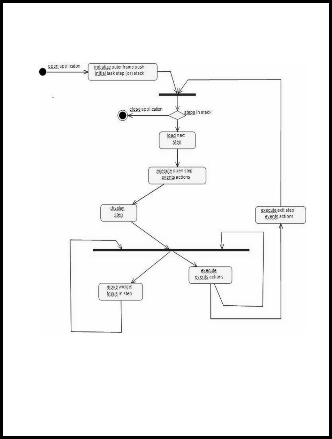
(IV) ACTIVITY DIAGRAM:
The activity diagram notation is an action, partition, fork join and
object node. Most of the notation is self explanatory, two subtle points. Once
an action finished, there is an automatic outgoing transaction. The diagram
can show both control flow and data flow.
Fig.4. ACTIVITY DIAGRAM

(V) CLASS DIAGRAM:
The class diagram, also referred to as object modeling is the main
static analysis diagram. The main task of object modeling is to graphically
show what each object will do in the problem domain. The problem domain
describes the structure and the relationships among objects.
Fig.5.CLASS DIAGRAM
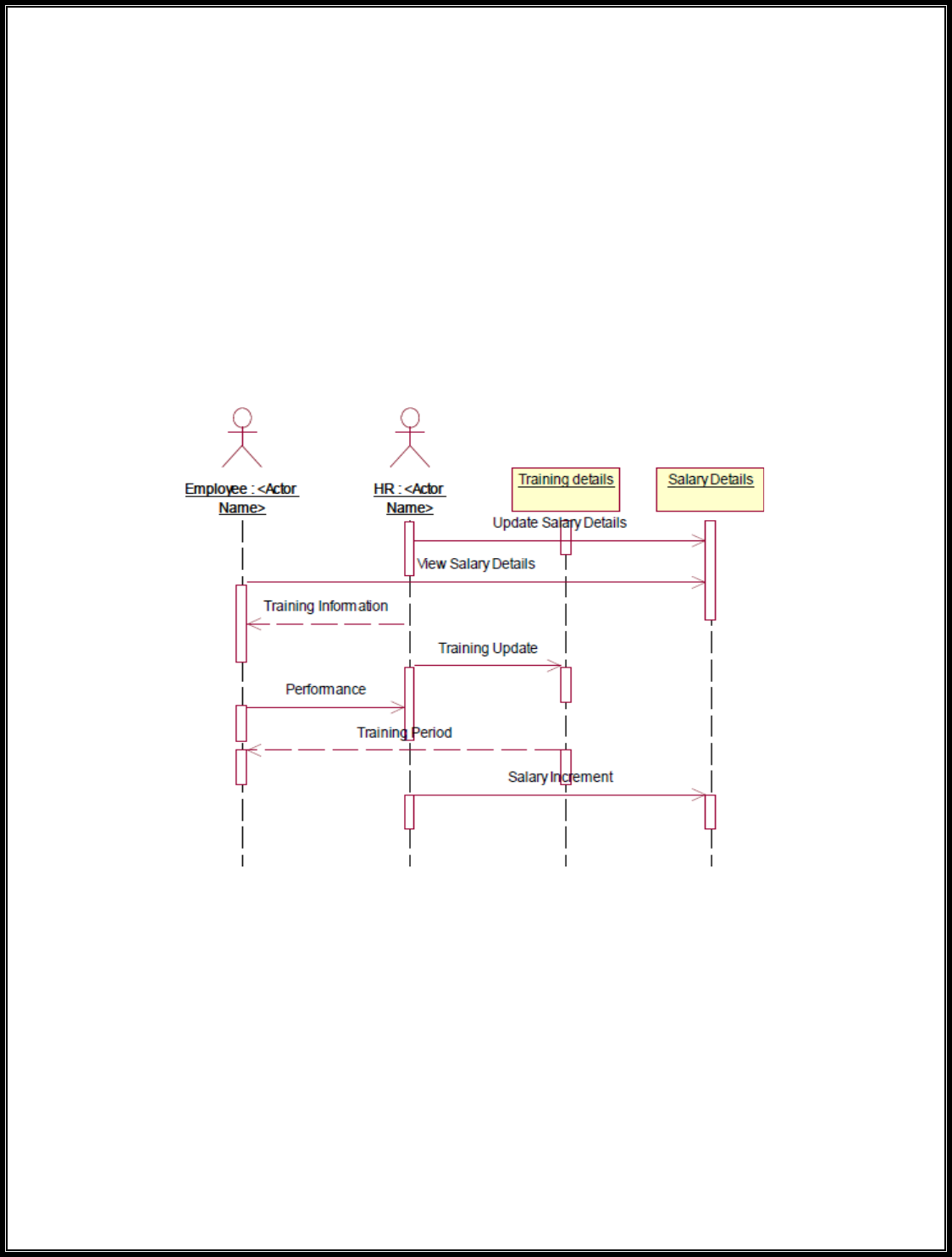
(VI) INTERACTION DIAGRAM:
A sequence diagram represents the sequence and interactions of a
given USE-CASE or scenario. Sequence diagrams can capture most of the
information about the system. Most object to object interactions and
operations are considered events and events include signals, inputs,
decisions, interrupts, transitions and actions to or from users or external
devices.
Fig.6.1.SEQUENCE DIAGRAM

Fig.6.2.COLLABORATION DIAGRAM
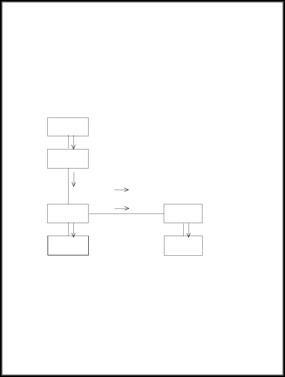
(VII) State Transition Diagram
States of object are represented as rectangle with round corner, the
transaction between the different states. A transition is a relationship
between two state that indicates that when an event occur the object moves
from the prior state to the subsequent.
Fig.7.STATE TRANSITION DIAGRAM

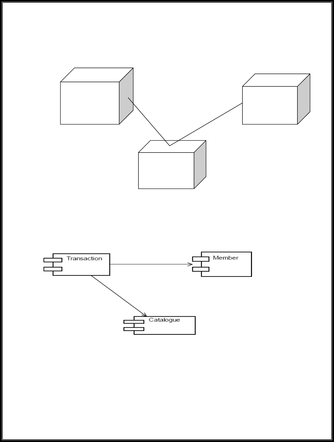
(VIII) DEPLOYMENT DIAGRAM AND COMPONENT DIAGRAM
HR recruits employee for a company employee recruited by HR goes
under training before actually working. Training period is given to the
employee with the training details. The salary details for the employee are
provided.
Fig.8.1.DEPLOYMENT DIAGRAM

COMPONENT DIAGRAM
The HR recruits, motivate and monitor the employee, HR also update
the salary details and training details for reference. The employee are those
who are recruited by HR and work for the company. The training details
provide employees with training details which is updated by HR
Fig.8.2.COMPONENT DIAGRAM
RESULT:
Thus the mini project for software personnel management system has
been successfully executed and codes are generated.

Ex. No:9
Date:
CREDIT CARD PROCESSING
AIM:
To create a system to perform the credit card processing
(I) PROBLEM STATEMENT:
Credit card processing through offline involves the merchant
collecting order information (including credit card numbers), storing this in a
database on your site, and entering it using their on-site merchant credit card
processing system. Takes time to manually enter credit card information for
each order. This solution creates following cons:
( II )SOFTWARE REQUIREMENT SPECIFICATION:
2.1 PRODUCT PERSPECTIVE
This solution involves signing up for a free Business Account. Once
this is done and the e-commerce site is properly configured, you can accept
payments from Visa, MasterCard, Amex, and Discover cards payments.
2.2 SOFTWARE INTERFACE
• Front End Client - The applicant and Administrator online
interface is built using
JSP and HTML. The Administrators's local interface is built using
Java.
• Web Server - Glassfish application server(SQL Corporation).
• Back End - SQL database.
2.3 HARDWARE INTERFACE

The server is directly connected to the client systems. The client
systems have access to the database in the server.
( III )USECASE DIAGRAM:
USE-CASE NAME: PAYMENT APPROVAL
The transaction details are recorded by the credit card processor and
results are securely relayed to the merchant. Merchant’s site receives
transaction result and does appropriate actions (e.g. saves the order & shows
message).
Fig.3. USECASE DIAGRAM FOR PASSPORT AUTOMATION
SYSTEM
(IV) CLASS DIAGRAM:

The class diagram, also referred to as object modeling is the main
static analysis diagram. The main task of object modeling is to graphically
show what each object will do in the problem domain. The problem domain
describes the structure and the relationships among objects.
The Credit Card Processing system class diagram consists of three
classes.
They are
Cashier
User
Authorization Service
Fig.4.CLASS DIAGRAM

(V) INTERACTION DIAGRAM:
Fig.5.1.SEQUENCE DIAGRAM
Fig.5.2.COLLABORATION DIAGRAM

Persistence
DBFacade
UI
Swing
CCP system
Technical Services
SOAP
Log4J
(VI) PARTIAL LAYERD LOGICAL ARCHITECTURE DIAGRAM
Domain
User
Purchase
Account Info
AutherizationSerivic
e
Reply
Merchant
Request
Receipt

(VII) DEPLOYMENT DIAGRAM AND COMPONENT DIAGRAM
Deployment diagrams are used to visualize the topology of the
physical components of a system where the software components are
deployed.
<<database>
>
: SQL
SQ HT
<<client
workstation
>>:Generic
<<server>>
Fig.7.1.DEPLOYMENT DIAGRAM
COMPONENT DIAGRAM
Component diagrams are used to visualize the organization and relationships
among components in a
Fig.7.2.COMPONENT DIAGRAM
RESULT:
Thus the mini project for credit card processing system has been
successfully executed and codes are generated.

Ex. No:10
Date:
AIM:
E-B OOK MANAGEMENT SYSTEM
To create a system to perform E- book Management System.
(I) PROBLEM STATEMENT:
An E- Book lends books and magazines to member, who is registered in
the system. Also it handles the purchase of new titles for the Book Bank.
Popular titles are brought into multiple copies. Old books and magazines are
removed when they are out or date or poor in condition. A member can
reserve a book or magazine that is not currently available in the book bank,
so that when it is returned or purchased by the book bank, that person is
notified. The book bank can easily create, replace and delete information
about the tiles, members, loans and reservations from the system.
(II) SOFTWARE RESOURCE SPECIFICATION:
2.0 OVERALL DESCRIPTION
Itwill describe major role of the system components and inter-
connections.
2.1 PRODUCT PERSPECTIVE
The ORS acts as an interface between the user and the 'e-book
manager'. This system tries to make the interface as simple as possible and at
the same time not risking the security of data stored in. This minimizes the
time duration in which the user receives the books or magazines.
2.2 SOFTWARE INTERFACE
Front End Client - The Student and Librarian online interface is built
using JSP and HTML. The Librarians local interface is built using Java.
Web Server - Glassfish application server (Oracle Corporation).
Back End - Oracle database
2.3 HARDWARE INTERFACE

The server is directly connected to the client systems. The client
systems have access to the database in the server.
(III) USE-CASE DIAGRAM:
Fig.3.USE-CASE DIAGRAM FOR E-BOOK SYSTEM
(IV) ACTIVITY DIAGRAM:

(V) CLASS DIAGRAM
The class diagram, also referred to as object modeling is the main
static analysis diagram. The main task of object modeling is to graphically
show what each object will do in the problem domain. The problem domain
describes the structure and the relationships among objects.
Fig.5.CLASS DIAGRAM FOR E-BOOK SYSTEM

(VI) INTERACTION DIAGRAM:
A sequence diagram represents the sequence and interactions of a
given USE-CASE or scenario. Sequence diagrams can capture most of the
information about the system. Most object to object interactions and
operations are considered events and events include signals, inputs,
decisions, interrupts, transitions and actions to or from users or external
devices.
An event also is considered to be any action by an object that sends
information. The event line represents a message sent from one object to
another, in which the “form” object is requesting an operation be performed
by the “to” object. The “to” object performs the operation using a method
that the class contains.
It is also represented by the order in which things occur and how the
objects in the system send message to one another.
The sequence diagram and collaboration diagram are given below.
Fig.6.1.SEQUENCE DIAGRAM

UI
Swing
E-Book system
Technical Services
Log4J
SOAP
Persistence
DBFacade
Fig.6.2.COLLABORATION DIAGRAM
(VII) PARTIAL LAYERD LOGICAL ARCHITECTURE DIAGRAM
Domain
Client
bill
Credit History
Order
Process
Balance

<<database>>
:MySQL
<<client
workstation>>:
GenericPC
SQL
HTTP
<<server>> :To
mcat6
(VIII) DEPLOYMENT DIAGRAM AND COMPONENT DIAGRAM
Deployment diagrams are used to visualize the topology of the
physical components of a system where the software components are
deployed.
Fig.8.1.DEPLOYMENT DIAGRAM
COMPONENT DIAGRAM
Component diagrams are used to visualize the organization and relationships
among components in a system.
Fig.8.2.COMPONENT DIAGRAM
RESULT:
Thus the mini project for E-Book System has been successfully
executed and codes are generated.

Ex.No: 11
Date:
RECRUITMENT SYSTEM
AIM:
To create an automated system to perform the Recruitment System
Process.
(I) PROBLEM STATEMENT:
The recruitment system allows the job seekers to enroll their names
through the process of registration. The employee also can get the list of
available candidates and shortlist for their company requirement. Once the
applicant enrolls he receives an id, which helps him in further
Correspondence. A fees amount is received from the job seekers for
enrollment. This system makes the task of the job seeker easier rather than
waiting in queue for enrollment. This also reduces the time consumption for
both for the job seeker and employee.
(II) SOFTWARE REQUIREMENT SPECIFICATION:
2.1 PRODUCT PERSPECTIVE
The PAS acts as an interface between the 'applicant' and the
'administrator'. This system tries to make the interface as simple as possible
and at the same time not risking the security of data stored in. This
minimizes the time duration in which the user receives the recruitment.
2.2 SOFTWARE INTERFACE
• Front End Client - The applicant and Administrator online
interface is built using JSP and HTML. The Administrators's local
interface is built using Java.
• Web Server - Glassfish application server (SQL Corporation).

• Back End - SQL database.
2.3 HARDWARE INTERFACE
The server is directly connected to the client systems. The client
systems have access to the database in the server.
( III )USECASE DIAGRAM:
The Recruitment Automation system use cases are:
Fig.3. UML USE CASE DIAGRAM

(IV) ACTIVITY DIAGRAM:
Fig.4. ACTIVITY DIAGRAM
(V) UML CLASS DIAGRAM:
The UML class diagram is to illustrate class interfaces and their actions.
They are used for static object modeling, we have already introduced and
used their UML diagram while domain modeling.

Fig.5. UML CLASS DIAGRAM
(VI) UML SEQUENCE DIAGRAM:
A sequence diagram illustrates a kind of format in which each object
interacts via message. It is generalize between two or more specialized
diagram.

Fig. 6.1SEQEUENCE DIAGRAM FOR Register:
Fig.6.2. SEQUENCE DIAGRAM FOR STATUS

Fig.6.3. SEQUENCE DIAGRAM FOR Admin
(VII) UML COLLABRATION DIAGRAM:
Communication diagram illustrate that object interact on a graph or network
format in which object can be placed where on the diagram. In collaboration
diagram the object can be placed in anywhere on the diagram. The
collaboration comes from sequence diagram.
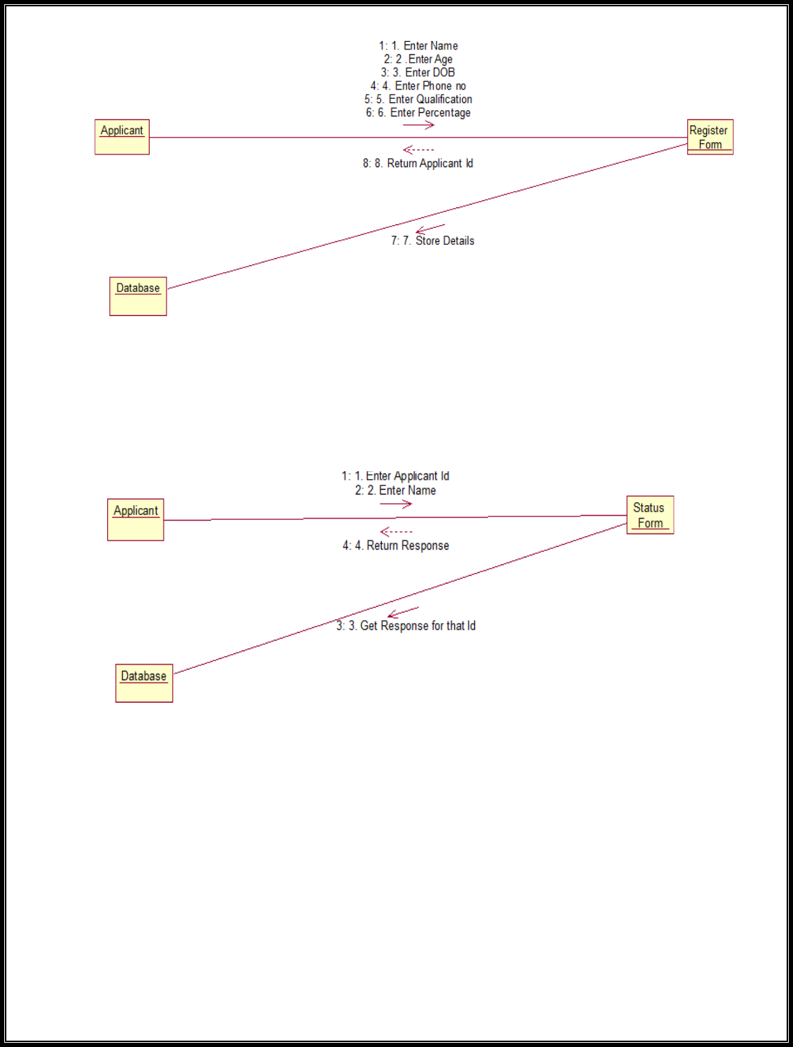
Fig.7.1COLLABRATION DIAGRAM For Register
Fig.7.2. COLLABORATION DIAGRAM FOR Status

Technical Services
SOAP
Log4J
Persistence
DBFacade
Fig.7.3.COLLABORATION DIAGRAM FOR Admin
(VIII) PARTIAL LAYERD LOGICAL ARCHITECTURE DIAGRAM:
UI
Swing
Recruitment
system
Text
Recruitment
Form
Domain
Candidate
Submit
Cancel
Status
Admin panel
send
Get status
delete
<<databas
e>>
:MySQL
<<client
workstati
on>>:Gen
SQ
H
<<server>
> :Tomca
t6
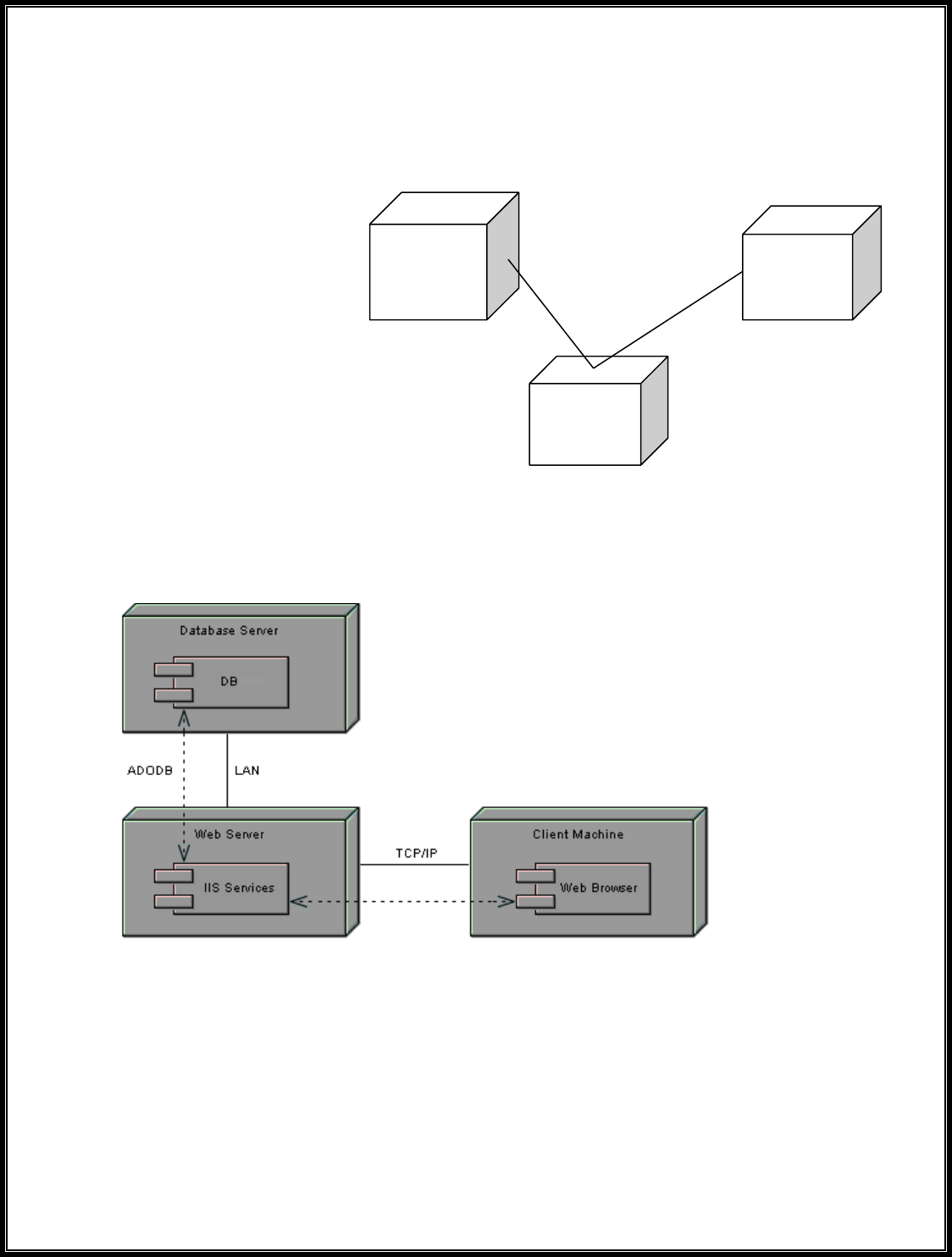
(IX) DEPLOYMENT DIAGRAM AND COMPONENT DIAGRAM
Deployment diagrams are used to visualize the topology of the
physical components of a system where the software components are
deployed.
Fig.9.1.DEPLOYMENT DIAGRAM
Component Diagram
Component diagrams are used to visualize the organization and
relationships among components in a system.
Fig.9.2.COMPONENT DIAGRAM
RESULT:
Thus the mini project for recruitment system has been successfully
executed and codes are generated.

Ex.No :12 FOREIGN TRADING SYSTEM
Date :
AIM
To design a project Foreign Trading System using Rational Rose
Software and to implement the software in Visual Basic
(I) PROBLEM STATEMENT
The steps involved in Foreign Trading System are:
The forex system begins its process by getting the username and password
from the trader. After the authorization permitted by the administrator, the
trader is allowed to perform the sourcing to know about the commodity
details.After the required commodities are chosen, the trader places the
order.The administrator checks for the availability for the required
commodities and updates it in the database. After the commodities are ready
for the trade, the trader pays the amount to the administrator.The
administrator in turn provides the bill by receiving the amount and updates it
in the database.The trader logouts after the confirmation message has been
received.
(II) SOFTWARE REQUIREMENT SPECIFICATION
ADMINISTRATOR
One who coordinates the entire trading
process.
DATABASE
All the transaction details are stored
here.
READER
Person who is viewing the website.
USER
The traders and the viewers are the
users.
SOFTWARE REQUIREMENT
SPECIFICATION
This software specification documents
full set of features and function for
foreign trading system.
FUNCTIONALITY
Transfer purchasing power between countries. Obtain credit for international
trade transactions. Minimize exposure to the risks of exchange rate changes.

FUNCTIONALITY REQUIREMENTS
Functional requirements refers to the functionality of the system. The
services that are provided to the trader who trades.
UML DIAGRAMS
The exporter submits the relevant documents to his buyer (banker) for getting the payment
for the goods exported.
(III) USE CASE DIAGRAM
CLASS DIAGRAM
A class diagram is a type of static structure diagram that describes the
structure of a system. The classes in the class diagram represent both the
main objects and or interactions in the application.The class diagram is
represented using rectangular boxes each of which contains three parts:

SEQUENCE DIAGRAM
A sequence diagram in unified modeling language is a kind of interaction
diagram that shows how processes operate with one another and in what
order. It is a construct of a Message Sequence Chart. Sequence diagrams are
sometimes called event diagrams, event scenarios, and timing diagrams.
This diagram shows a parallel vertical lines called lifelines. There are two
dimensions in this diagram
1. Vertical dimension-represents time.
2. Horizontal dimension-represent different object

TraderTraderAdministratorAdministratorDatabaseDatabaseLoginSourcingPl
ace orderUpdateorderPay update account details bill logout
COLLABORATION DIAGRAM
A collaboration diagram belongs to a group of UML diagrams called
Interaction Diagrams. collaboration diagrams, like sequence diagrams, show
how the objects interact over the course of time. collaboration diagrams
show the sequence by numbering the messages on the diagram.

DOCUMENTATION OF COLLABORATION DIAGRAM
The collaboration diagram shows how the trader performs the sourcing and
places order for which the administrator provides the bill and updates it in
the database.
STATE CHART DIAGRAM
The state chart is used to model dynamic nature of a system. They define
different states of an object during its lifetime. And these states are changed
by events. So these diagrams are useful for reactive systems i.e.., a system
that responds to external or internal events. It describes the flow of control
from one state to other state. The initial state is represented using the small
dot. The final state is represented using a circle surrounded by a small dot
DOCUMENTATION OF STATE CHART DIAGRAM
The state diagram represents the following states.
• The trader logins the register in the first state and performs sourcing in the
second state.
• The trader places the order in the third state.
• The trader receives the bill in the fourth state and pay the required amount
in fifth state.
• The trader logouts from the system in the sixth state
ACTIVITY DIAGRAM
This diagram represents the graphical representation of workflows of
stepwise activities and actions with support for choice, iteration and
concurrency. It shows the overall flow of control.
DOCUMENTATION OF ACTIVITY DIAGRAM
This activity diagram represents the flow of stepwise activities performed in
foreign trading system.
• The first action represents the trader logins to the system.
• The second action is the place where the trader places the order.
• The decision state is the state where the trader decides to place the order.
• If the trader places the order, fill the form for the required commodities.

• The next activity is that the administrator provides the bill for those
commodities.
• The trader pays for the bill and logout from the system.
COMPONENT DIAGRAM
A component diagram depicts how the components are wired together to
form larger components and or software systems. Components are wired
together by using an assembly connector to connect the required interface of
one component with the provided interface of another component.
DOCUMENTATION OF COMPONENT DIAGRAM
The main component in the component diagram is foreign trading system.
The trader who come to do the trading process and administrator who
manages all the other processes is the sub components.
DEPLOYMENT DIAGRAM
A deployment diagram models the physical deployment of artifacts on nodes.
The nodes appear as boxes, and the artifacts allocated to each node appear as
rectangles within the boxes. Nodes may have sub nodes, which appear as
nested boxes.

DOCUMENTATION OF DEPLOYMENT DIAGRAM
The processor in this diagram is the foreign trading system. The devices are
the trader and administrator who perform the main activities in the system.
PACKAGE DIAGRAM
A package diagram in the unified modeling language depicts the
dependencies between the packages that make up a model. It provides a way
to group the elements. There are three types of layers in package diagram.
They are
• User interface layer
• Domain layer
• Technical services layer
User interface layer
The user interface layer may call upon its directly subordinate application
logic layer, and also upon elements of a lower technical service layer, for
logging and so forth.
Domain layer
Software objects representing domain concepts (for example, a software
class administrator) that fulfill application requirements, such as tracing
order and providing the bill.
Technical services layer

General purpose objects and subsystems that provide supporting technical
services, such as interfacing with a database or error logging.These services
are usually application-independent.
DOCUMENTATION OF PACKAGE DIAGRAM
The three layers in the foreign trading system are
• User interface layer – consists of web and login. This layer describes how
the trader logins to the website and trades for the commodities.
• Domain layer – shows the activities that are performed inside the trading
system. The activities are place order, pay for the bill and logouts.
• Technical service layer – The sourcing and updating the details are
performed in this layer.
RESULT
Thus the mini project for foreign trading system has been successfully
executed and codes are generated.

Ex. No: 13 CONFERENCE MANAGEMENT SYSTEM
Date:
AIM
To develop a project on Conference management system using
Rational Rose Software.
( I )PROBLEM STATEMENT
The process of the candidates is to login the conference system and submit
the paper through online. Then the reviewer reviews the paper and sends the
acknowledgement to the candidate either paper selected or rejected. This
process of on conference management system are described sequentially
through following steps,
• The candidate login to the conference management system.
• The paper title is submitted.
• The paper is been reviewed by the reviewer.
• The reviewer sends acknowledgement to the candidate.
• Based on the selection, the best candidate is selected.
• Finally the candidate registers all details.
(II )SOFTWARE REQUIREMENT SPECIFICATION
CANDIDATE
The candidate can login and submit the
paper to the reviewer. After getting
acknowledgement the candidate will
submit the revised and camera ready paper
then registration process
will be carried out.
REVIEWER
Reviewer will reviews the paper and
sending acknowledgement to the candidate
DATABASE
Database is used to verify login and store
the details of selected candidates.

SOFTWARE REQUIREMENT
SPECIFICATION
This software specification documents full
set of features
and function for conference management
system.
PURPOSE
The purpose of the conference management system is that the system can
easily review the process. The main process in this document is the
submission of paper by the candidate, reviewing process by the reviewer and
sending of acknowledgement to the candidates whose paper is selected.
SCOPE
The scope of this conference management process is to select the best
candidate from the list of candidates based on their performance in the
process.
FUNCTIONALITY
The main functionality of conference system is to select the candidate for the
presentation in conference.
USABILITY
The user interface to make the process should be effective that is the system
will help the candidates to register easily. The system should be user friendly.
PERFORMANCE
It describes the capability of the system to perform the conference process of
the candidate without any error and performing it efficiently.
RELIABILITY
The conference system should be able to serve the applicant with correct
information and day-to-day update of information.
FUNCTIONAL REQUIREMENTS
Functional requirements are those that refer to the functionality of the
system that is the services that are provided to the candidate who register for
the conference.
UML DIAGRAMS

The following UML diagrams describe the process involved in the
conference management system.
USE CASE DIAGRAM
A use case is a methodology used in system analysis to identify, clarify, and
organize system requirements. The use case is made up of a set of possible
sequences of interactions between systems and users in a particular
environment and related to a particular goal. It is represented using ellipse.
Actor is any external entity that makes use of the system being modeled. It is
represented using stick figure.
DOCUMENTATION OF USE CASE DIAGRAM
The actors in this use case diagram are candidate, reviewer and database.
The use cases are the activities performed by actors.
The actors in this use case diagram are
• Candidate - Logins the conference system and submits the paper then do
the registration process.
• Reviewer – Review the paper , select best candidate and send
acknowledgement to them.
• Databases - verify the login and register details and selected candidate
details are stored in it.
The use cases in this use case diagram are
• Login - Candidate enter their username and password to login to the
conference system.
Paper sumbission– Candidate submits the paper.
• Review the paper– The paper is been reviewed by the reviewer and the
paper is selected.
• Paper confirmation details – The reviewer can send the confirmation
details to the candidate.

• Revised and camera ready paper – After the paper is selected and the
camera ready paper should be submitted to the reviewer by candidate.
• Registration – After submitting the revised paper the candidate wants to
register.
CLASS DIAGRAM
A class diagram in the unified modeling language (UML) is a type of static
structure diagram that describes the structure of a system by showing the
system's classes, their attributes, and the relationships between the classes. It
is represented using a rectangle with three compartments. Top compartment
have the class name, middle compartment the attributes and the bottom
compartment with operations.
DOCUMENTATION OF CLASS DIAGRAM
This class diagram has three classes candidate, reviewer and database.
• Candidate – Its attributes are name ,collegename , department , paper title.
The operations performed in the candidate class are login, submit the paper,
submit revised and camera ready paper and registration.

• Reviewer – Its attributes are name, department, reviewer ID The
operations performed are review the paper and send the paper confirmation
details.
• Database –The operations performed are storing candidate details and
verifying login .
SEQUENCE DIAGRAM
A sequence diagram in Unified Modeling Language (UML) is a kind of
interaction diagram that shows how processes operate with one another and
in what order. It is a construct of a Message Sequence Chart. There are two
dimensions.
1. Vertical dimension-represent time.
2. Horizontal dimension-represent different objects.

SEQUENCE DIAGRAM FOR SUBMITTING PAPER
DOCUMENTATION OF SEQUENCE DIAGRAM
LOGIN
This sequence diagram describes the sequence of steps to show
• The candidate login in to the conference system and register for job.
• The verification done in the database .
PAPER SUBMISSION
This sequence diagram shows steps to show
• The candidate sumbit the paper.
• The reviewer reviews the paper and sends acknowlegement to the
candidate.
• The candidate submits revised and camera ready paper.
• This candidate will registers their detials.
COLLABRATION DIAGRAM
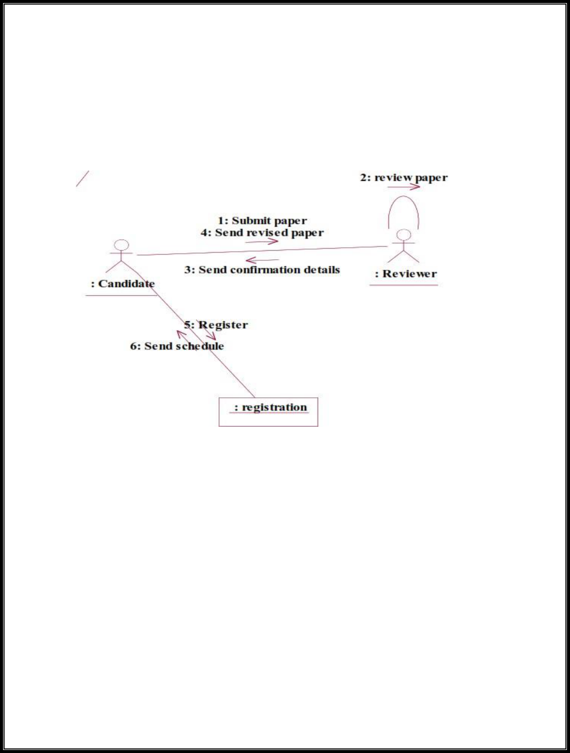
A collaboration diagram, also called a communication diagram or interaction
diagram,. A sophisticated modeling tool can easily convert a collaboration
diagram into a sequence diagram and the vice versa. A collaboration
diagram resembles a flowchart that portrays the roles, functionality and
behavior of individual objects as well as the overall operation of the system
in real time.
DOCUMENTATION OF COLLABRATION DIAGRAM
LOGIN
This collaboration diagram is to show how the applicant login in the
conference system. Here the sequence is numbered according to the flow of
execution.
PAPER SUBMISSION
This collaboration diagram is to show the submitting paper process of the
candidate for the conference. The flow of execution of this selection process
is represented using the numbers.
STATE CHART DIAGRAM

The purpose of state chart diagram is to understand the algorithm involved
in performing a method. It is also called as state diagram. A state is
represented as a round box, which may contain one or more compartments.
An initial state is represented as small dot. A final state is represented as
circle surrounding a small dot.
DOCUMENTATION OF STATE CHART DIAGRAM
This state diagram describes the behaviour of the system.
• First state is login where the candidate login to the conference system.
• The next state is submitting the paper .
• Then review the paper if it is selected the process will continue..
• The candidate should submit revised and camera ready paper.
ACTIVITY DIAGRAM
Activity diagrams are graphical representations of workflows of stepwise
activities and actions with support for choice, iteration and concurrency. In
the Unified Modeling Language, activity diagrams can be used to describe
the business and operational step-by-step workflows of components in a
system. An activity diagram shows the overall flow of control. An activity is
shown as an rounded box containing the name of the operation.
DOCUMENTATION OF ACTIVITY DIAGRAM
This activity diagram flow of stepwise activities performed in recruitment
system.
• First the candidate login to the database.
• Then the candidate should submit the paper.
• If it is selected the acknowledgement will send to the candidate.
• After submitting revised paper the registration proces will be done.
COMPONENT DIAGRAM

The component diagram's main purpose is to show the structural
relationships between the components of a system. It is represented by
boxed figure. Dependencies are represented by communication association.
DOCUMENTATION OF COMPONENT DIAGRAM
The main component in this component diagram is conference management
system. And submit the paper, review the paper and registration.
DEPLOYMENT DIAGRAM
A deployment diagram in the unified modeling language serves to model the
physical deployment of artifacts on deployment targets. Deployment
diagrams show "the allocation of artifacts to nodes according to the
Deployments defined between them. It is represented by 3-dimensional box.
Dependencies are represented by communication association.

DOCUMENTATION OF DEPLOYMENT DIAGRAM
The processor in this deployment diagram is the conference management
system which is the main part and the devices are the candidate, appear for
do conference , reviewer will reviews paper , database will store all details
which are the some of the main activities performed in the system.
PACKAGE DIAGRAM
A package diagram in unified modeling language that depicts the
dependencies between the packages that make up a model. A Package
Diagram (PD) shows a grouping of elements in the OO model, and is a
Cradle extension to UML. PDs can be used to show groups of classes in
Class Diagrams (CDs), groups of components or processes in Component
Diagrams (CPDs), or groups of processors in Deployment Diagrams (DPDs).
DOCUMENTATION OF PACKAGE DIAGRAM
The three layers in the online recruitment system are
• The User interface layer - consists of the web and login. This layer
describes how the candidate login.
• The Domain layer – shows the activities that are performed in the
conference management system. The activities are paper submission , review
paper , registration.
• The Technical service layer - the verification details and the selected
candidate details will stored into the database.

RESULT
Thus the mini project for Conference management system has been
successfully executed and codes are generated.
Ex.No:14 BPO MANAGEMENT SYSTEM
Date:
AIM:
To implement a software for BPO management system
(I) PROBLEM STATEMENT:
With the reduction in communication costs and improved bandwidths
and associated infrastructure, BPO as a segment is witnessing a massive
growth. One of the key challenges that BPO companies that provide data
entry/data validation services is an efficient and effective way of getting the

source documents from different customers and accurately route the same to
different operators for processing.
(II) SOFTWARE REQUIREMENT SPECIFICATION:
2.1 PRODUCT PERSPECTIVE
The BPOS acts as an interface between the 'client' and the
'administrator'. This system tries to make the interface as simple as possible
and at the same time not risking the security of data stored in. This
minimizes the time duration in which the user receives the documents.
2.2 SOFTWARE INTERFACE
• Front End Client - The applicant and Administrator online
interface is built using JSP and HTML. The Administrators's local
interface is built using Java.
• Web Server - Glassfish application server (SQL Corporation).
• Back End - SQL database.
2.3 HARDWARE INTERFACE
The BPO system’s server is directly connected to the client systems
via ftp. The client systems have access to the database in the server.
( III )USECASE DIAGRAM:
The BPO management system use cases are:

Fig.3. UML USE CASE DIAGRAM
(IV) UML CLASS DIAGRAM:

The UML class diagram is to illustrate class interfaces and their actions.
They are used for static object modeling, we have already introduced and
used their UML diagram while domain modeling.
Fig.5. UML CLASS DIAGRAM

(V) UML SEQUENCE DIAGRAM:
A sequence diagram illustrates a kind of format in which each object
interacts via message. It is generalize between two or more specialized
diagram.
Fig. 5.1SEQEUENCE DIAGRAM
Communication diagram illustrate that object interact on a graph or network
format in which object can be placed where on the diagram. In collaboration
diagram the object can be placed in anywhere on the diagram. The
collaboration comes from sequence diagram.

Fig.5.2COLLABRATION DIAGRAM
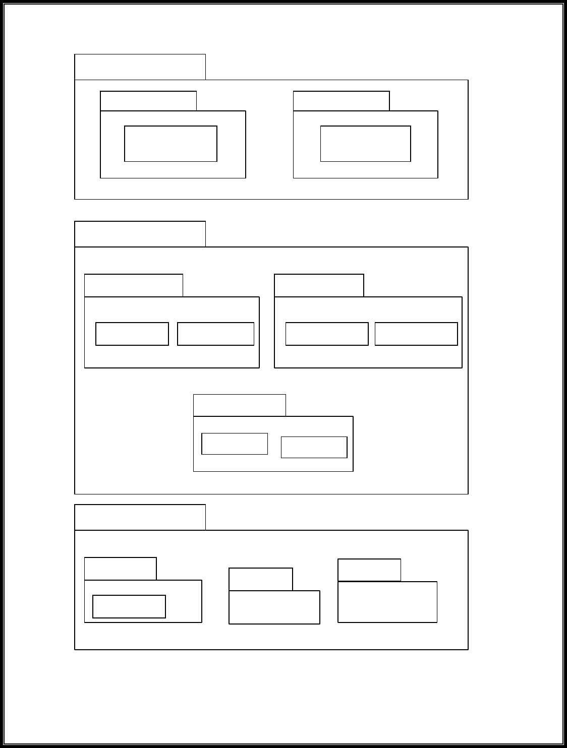
UI
Text
Swing
Recruitment
Form
BPOS
Domain
Client
Admin
BPOS
Feedback
Upload
OCR
Download
Data Entry
QC
Technical Services
SOAP
Log4J
Persistence
DBFacade
(VI) PARTIAL LAYERD LOGICAL ARCHITECTURE DIAGRAM:

<<database>>
:SQL
<<client
workstation>>:
GenericPC
SQL
FTP
<<server>>
(VIII) DEPLOYMENT DIAGRAM AND COMPONENT DIAGRAM
Deployment diagrams are used to visualize the topology of the
physical components of a system where the software components are
deployed.
Fig.9.1.DEPLOYMENT DIAGRAM
Component Diagram
Component diagrams are used to visualize the organization and
relationships among components in a system.
RESULT :
Thus the mini project for BPO management system has been
successfully executed and codes are generated.

Ex.No:15 LIBRARY MANAGEMENT SYSTEM
Date:
AIM
To design an object oriented model for Library Management System using
Rational Rose software and to implement it using Java.
PROBLEM STATEMENT
The library management system is a software system that issues books and
magazines to registered students only. The student has to login after getting
registered to the system. The borrower of the book can perform various
functions such as searching for desired book, get the issued book and return
the book.
CLASS DIAGRAM
A class diagram in the unified modeling language is a type of static structure
diagram that describes the structure of a system by showing the system’s
classes, their attributes, operations and the relationships among objects. The
library management system makes use of the following classes user,

login
enter name and password
<<actor>>
projection of
display page
user
requesting for book
display book details
search for book
librarian
issue book
return book
maintain database
DBA
librarian, system and DBA.
USE CASE DIAGRAM
Use case is a list of actions or events. Steps typically defining the
interactions between a role and a system to achieve a goal. The use case
diagram consists of various functionality performed by actors like user,
librarian, system and DBA.

DEPLOYMENT DIAGRAM
Deployment diagram is a structure diagram which shows
architecture of the system as deployment of software artifacts to
deployment target. It is the graph of nodes connected by
communication association. It is represented by three
dimensional box. The device node is library management system
and execution environment nodes are user, librarian, system and
DBA.
COMPONENT DIAGRAM
Component diagram shows the dependencies and
interactions between software components. Component diagram
carries the most important living actors of the system i.e, user,
librarian and DBA.

login
enter
details
requesting
for book
display book
details
logout
return book
issue book
search
book
STATECHART DIAGRAM
State chart diagram is also called as state machine diagram.
The state chart diagram contains the states in the rectangular
boxes and the states are indicated by the dot enclosed. The state
chart diagram describes the behavior of the system. The state
chart diagram involves eight stages such as login, enter details,
requesting for book, display book details, search book, issue
book, return book and logout.
COLLABORATION DIAGRAM
Like sequence diagram collaboration diagrams are also called as interaction
diagram. Collaboration diagram convey the same informations as sequence
diagram but focus on the object roles instead of the times that messages are
sent. Here the actions between various classes are represented by number
format for the case of identification.
librarian
DBA
user
library management
system

SEQUENCE DIAGRAM
A sequence diagram represent the sequence and interactions of a given use
case or scenario. Sequence diagram capture most of the information about
the system. It is also represent in order by which they occur and have the
object in the system send message to one another. Here the sequence starts
with interaction between user and the system followed by database. Once the
book have been selected the next half of sequence starts between librarian
and user followed by database.

ACTIVITY DIAGRAM
Activity diagram are graphical representation of workflows of stepwise
activities and actions with support for choice, iteration and concurrency.
Here in the activity diagram the user login to the system and perform some
main activity which is the main key element to the system.
RESULT
Thus the various UML diagrams for library management system was drawn
and the code was generated successfully.

Ex.No:16 STUDENT INFORMATION SYSTEM
Date:
AIM
To design an object oriented model for Student information system using
Rational Rose software.
PROBLEM STATEMENT
The student must register by entering the name and password to login the
form. The admin select the particular student to view the details about that
student and maintaining the student details. This process of student
information system is described sequentially through following steps. The
student registers the system. The admin login to the student information
system. He/she search for the list of students. Then select the particular
student. Then view the details of that student. After displaying the student
details then logout.
CLASS DIAGRAM
The class diagram is the graphical representation of all classes used in the
system. The class diagram is drawn as rectangular box with three
components or compartments like class name, attributes and operations. The
student information system makes use of the following classes like student,
staff, system, DBA and server.

COLLABORATION DIAGRAM
A Collaboration diagram represents the collaboration in which is a set of
objects related to achieve a desired outcome. In collaboration, the sequence
is indicated by numbering the message several numbering schemes are
available. Login, request access, allow access, display, view details, logout,
login, request access, allow access, display, enter profile, enter mark,
provide data, logout, store data, update data.

SEQUENCE DIAGRAM
A Sequence diagram represent the sequence and interaction
of a given usecase or scenario. Sequence diagram capture most of
the information about the system. Here the sequence starts
between the student and the system. The second half of interaction
takes place between staff and system then by police and followed

by database. The student first login to the system and then view
the details of the details. Staff login to the system enter mark and
enter the details of the student. DBA store and update the details
of the student.
COMPONENT DIAGRAM
Component diagram carries the major living actors of the
system. The component diagram main purpose is to show the

DBA
student
staff
student information
system
structural relationship between components of the system.The
main component of the system is student information system and
the other components of the system are student, staff and DBA.
USE CASE DIAGRAM
Use case diagram is a graph of actors, a set of use cases, association between
the actors and the use cases and generalization among the cases. Use case
diagram is a list of actions or events. Use case diagram was drawn to
represent the static design view of the system. Steps typically defined the
interactions between a role and a system to achieve a goal. The use case
diagram consists of various functionality performed by the actors like
student, staff, system, DBA and server. The use case diagram consists of
various functionality like login, display, enter profile, enter mark, view
details, update details, allow access, request access, store details, logout.
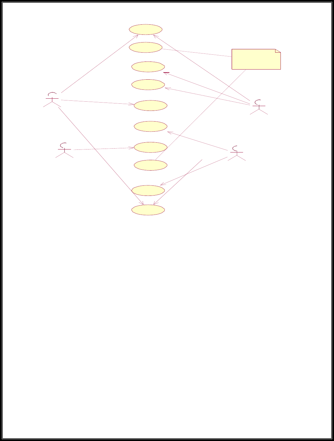
DEPLOYMENT DIAGRAM
Deployment diagram shows the configuration of runtime
processing elements and the software components processes and
objects that live in them. Component diagram are used in
conjunction with deployment diagram to show how physical
modules code are distributed on various hardware platform. The
processor node in the system is student information system and
the execution environment nodes or device nodes are student,
staff and DBA.
login
display
<<actor>>
projection of
student
information
enter profile
enter mark
s tudent
view details
staff
update details
allow acces s
server
DBA
reques t access
store data

login
enter
marks
enter
profile
view details
logout
store
details
update
details
STATE CHART DIAGRAM
A State chart diagram is also called as state machine diagram. The state
chart contains the states in the rectangular boxes and the states are indicated
by the dot enclosed. The state chart diagram describes the behavior of the
system. The state chart involves six stages such as login, enter mark, enter
profile, view details, provide details, update details, store details and logout.
ACTIVITY DIAGRAM
Activity diagram are graphical representation of stepwise

activities and actions with support for choice, interaction and
concurrency. Here in the activity diagram the student login to the
system and view the details of the student. The staff login to the
system for entering the student details and update the details in the
database. The final interaction is the DBA store the details of the
student.
RESULT
Thus the various UML diagrams for student information
system were drawn and code was generated successfully.

VIVA QUESTION
Ex.no 1: Passport automation system.
1.
What is Object-Oriented Analysis and Design?
2.
What is Class diagram?
3.
What is Interaction diagram?
4.
What is Sequence diagram?
5.
What are the three ways and perspectives to Apply UML?
Ex.no 2: Book bank
1.
What is use case?
2.
What are Actors?
3.
What is Activity diagram?
4.
What is Component diagram?
5.
What is Deployment diagram?
Ex.no 3: Exam registration
1.
Explain about exam registration scenario?
2.
What is Inception?
3.
What is object?
4.
What is UML?
5.
What are the goals of UML?
Ex.no 4: Stock maintenance system.
1.
What is Collaboration diagram?
2.
What is State Chart diagram?
3.
What is a scenario?
4.
What tests can help find useful use cases?
5.
What are Three Kinds of Actors?
Ex.no 5: Online course reservation system
1.
What is Package diagram?
2.
Explain the include relationship.
3.
Explain the extend relationship.
4.
What is the generalization relationship?
5.
What is meant by POS system?
Ex.no 6: Airline/Railway reservation system
1. What do you mean by the term elaboration?
2. Enlist various tasks that are involved in elaboration.
3. What is domain model?
4. Why domain model is referred as visual dictionary?
5. How to create domain model?
Ex.no 7: Software personnel management system
1.
Define conceptual classes.
2.
What are description classes?
3.
What is association?
4.
What is attributes?
5.
Define aggregation and composition.
Ex.no 8: Credit card processing
1.
Differentiate single and multiple inheritances.
2.
Distinguish between method and message in object.
3.
When to create a subclass of superclass?
4.
How to create instance?

5.
Give a sample category list for identifying conceptual classes
Ex.no 9: e-book management system
1.
What is design pattern ?
2.
Write notes on pattern.
3.
When to use pattern ?
4.
What is GRASP ?
5.
Define the concept of creator ?
Ex.no 10: Recruitment system
1.
Explain about Recruitment system.
2.
Define Modular Design.
3.
What is Observer Pattern?
4.
List out the types of Coupling.
5.
List out the four main benefits in Design Pattern?
Ex.no 11: Foreign trading system
1.
Define Behavioral.
2.
Define Creational.
3.
What is meant by Low Coupling ?
4.
Define Structural Pattern.
5.
Define Factory Method.
Ex.no 12: Conference management system
1.
What is Information Expert?
2.
Define Singleton Pattern.
3.
What do you mean by High Cohesion?
4.
Define Modular Design
5.
Mention Interface and Domain Layer responsibilities
Ex.no 13: BPO management system
1.
List the relationships used in class diagram.
2.
What is use of system sequence diagram?
3.
What do you mean by sequence number in UML? Where and for what it is used ?
4.
Define package and draw the UML notation for package?
5.
Differentiate sequence and communication diagram.
Ex.no 14: Library management system
1.
Explain about Library management system.
2.
Define component with example.
3.
Define System Events and the System Boundary.
4.
What is meant by Inter-System SSDs?
5.
What is meant by link?
Ex.no 15: Student information system
1.
What are steps for mapping design to coding?
2.
What are the issues in OO Testing?
3.
List the four level of OO testing.
4.
Define GUI Testing
5.
What is regression testing?
