
Technological University Dublin Technological University Dublin
ARROW@TU Dublin ARROW@TU Dublin
Reports
School of Surveying and Construction
Management (Former DIT)
2014
A Review of Process and Product Systems in Construction A Review of Process and Product Systems in Construction
Charles Anthony Mitchell
Technological University Dublin
Follow this and additional works at: https://arrow.tudublin.ie/beschrecrep
Part of the Other Engineering Commons
Recommended Citation Recommended Citation
Mitchell, C.A (2014)
A Review of Process and Product Systems in Construction
, University of Salford, 28th
April 2014. doi:10.21427/9v4e-cd12
This Report is brought to you for free and open access by the School of Surveying and Construction Management
(Former DIT) at ARROW@TU Dublin. It has been accepted for inclusion in Reports by an authorized administrator of
ARROW@TU Dublin. For more information, please contact arrow[email protected], [email protected],

A Review of Process and Product Systems in Construction.
Introduction –
This paper was produced as part of the coursework associated with a Masters in Quantity
Surveying (Mechanical and Electrical) undertaken by the Author. The aim of the research was
to study and review 1) processes and sub-processes in the pre-construction phase, 2) risk
analysis in the project and 3) the use of off-site construction in relation to an iconic structure
of the author’s choice. In the absence of information the author was permitted to make
assumptions about the processes involved as long as these were qualified within the text.
The author chose the Aviva stadium, Dublin 4 as the iconic structure and due to its design and
the controversy which surrounded its redevelopment.
Chapter 1 – The Aviva Stadium Dublin; Iconic by its very nature.
The original stadium at Lansdowne road was the brain child of Henry William Dunlop, an
outstanding young athlete. Dunlop is credited with organising the first All-Ireland Athletics
Championships. The venue was designed as a multi-sport venue catering for athletics, cricket,
crochet, archery, tennis and football. The stadium opened in 1872 and the first rugby match
was played in 1876. This was an inter-provincial match between Leinster and Ulster.
In 1878 the first of many international rugby matches was held in Lansdowne road. The Irish
Rugby Football Union (IRFU) secured a lease on the stadium from the Pembroke estate in the
early 1900s.
The first international soccer match took place in 1971 when Ireland played Italy in a friendly.
In the early 1980s the Irish football team made the original incarnation of Lansdowne road
stadium its home. At this point the stadium was considered the oldest sports stadium in
Europe.
The stadium has also played host to many non-sporting distinguished guests such as Frank
Sinatra, Sammy Davis Jnr, Celine Dion, Neil Diamond, The Eagles and U2, but to name a few.
As the city of Dublin developed and expanded the stadium became nestled in the heart of a
high end suburb which is home to many highflying business people and embassies.
The redevelopment of Lansdowne road was many years in the planning and was plagued with
controversy due to its history and location. Locals were concerned about the effects of the
proposed redevelopment and as a result the redevelopment was delayed for many years.
The final grant of planning permission was received in early 2007. Works commenced on site
in May 2007 and continued until April 2010. The works consisted of the demolition of the
existing stadium and construction of a new state of the art stadium and conference centre.
The new development contains 51,700 seats in a continuous curvilinear shaped stand which
encloses all four sides of the grounds. The design was developed to provide the maximum
amount of daylight to the pitch whilst maintaining daylight to the neighbouring area. The
project cost €410 million. The site is 63,802sq.m in area and the development covers nearly
all of this area.

The redevelopment included the demolition and recycling of the existing stadium, 5,000
tonnes of structural steel, 8,000 precast concrete units manufactured off-site and 72,000
tonnes of concrete cast in-situ on site, (www.avivastadium.ie).
The stadium was rebranded the Aviva Stadium, Dublin in the latter part of the redevelopment
and has continued its iconic status to this date.
The redevelopment has won many awards such as:
British Construction Industry Award (BCIA) for best international project 2011.
Royal Institute of British Architects (RIBA) Award – projects in the European Union Region
2011.
Winner Irish Concrete Society Awards – Building Category and Overall Winner 2010.

Chapter 2 – Task 1 – Describe and map the main processes and sub-processes in the pre-
construction stage.
The following series of diagrams seek to map the main processed and sub-processed in the
preconstruction stage of the Aviva Stadium, Dublin. It is important to note that many of the
points raised regarding the pre-construction stage of the redevelopment of the Aviva Stadium
Dublin within this chapter are founded on presumptions made by the author unless otherwise
noted.
This iconic project was years in the making and was in the public eye from the moment the
idea of the project was conceived.
Fig 1. A-0 Aviva Stadium (Context) – Level 0 (Source – Author)
The diagram above, Fig 1, outlines the pre-construction process as a whole. The process in
question is the planning and design of the new Aviva Stadium Dublin and this can be described
as the function.
On the left of the diagram we see the start point. These are known as inputs. The first input
is the client brief, the demolition of the existing stadium and replacement with a new state of
the art facility of provincial and international rugby and soccer. The new facility also must
provide alternative uses as a conference and concert venue.
The diagram also shows, on the left, the issues which the brief will have. These issues are
namely the location, site constraints, neighbours and working hours. These are more inputs
into the process.
The arrow leaving on the right shows the output. This is the data or object produced by the
function. There may be multiple outputs produced by the function.
At the bottom of the diagram is seen the input of the members of the Design Team. It is noted
that the whole project team is assembled as the pre-planning and design team as a whole.
This is a client requirement due to the level of co-ordination such a project requires.
Arrows entering from the bottom side of the function box represent the mechanisms.
Mechanisms can be described as resources used by the function but not consumed. In this
case the mechanism is the whole design team. All the team members bring a magnitude of
resources and knowledge, both tacit and explicit. The arrow leaving the bottom of the
function box is known as a call and shows the link between the function and other model(s).
The arrows which enter at the top of the function box are known as controls and represent
conditions required in order to produce the correct outputs. In this instance the controls
relate to building regulations, the client’s requirements, planning legislations, the site
constraints and site environment.
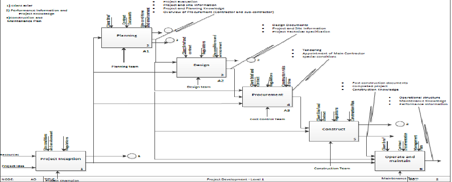
Fig 2. Project Development – Level 1 (Source – Author)
The diagram in Fig.2 is known as a child diagram and follows on from the diagram in Fig.1, the
parent diagram. This diagram gives an overview of the project.
Reading from the left we see the project inception and all the processes required to produce
the product. In this case a fully functional facility as required by the client brief. The main
functions are outlined from point 1 to 6 inclusive.
Each function, as noted, shows its inputs and outputs as wells as all associated controls and
mechanisms. Each function has a box number outlining that it is the first step in the process.
Beneath the box another reference may be found which outlines the major sub-functions to
be found in child diagrams.
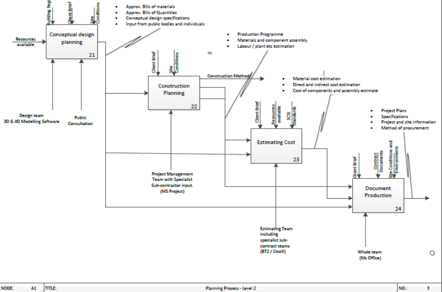
Fig 3. Planning Process – Level 2 (Source – Author)
The planning process diagram, Fig 3, is the first of the level 2 diagrams and is a child of the
project development level 1 diagram.
The first function is the Conceptual Design Planning; here we investigate the resources
available namely. The controls are shown at the top of the function box and include
regulation, brief and site conditions. But at this time no conceptual design is available. We
see the design team input entering from the bottom of the function box. The author has
presumed that both 3 Dimensional and 4 Dimensional software packages are used to create
the concept drawings. The initial plan also takes into account the need for public consultation
from a very early point in the design process. This issue will be discussed in more detail in
later chapters. The main reason for so much early input from so many key players and
stakeholders was required to limit exposure to risk and to secure the future of the
development.

In the second function, Construction Planning, it is envisaged that the whole project
management team with input from all specialist sub-contractors will be required. The author
has made the presumption that the project management team will use programmes such as
MS Project to programme the project. This will be done in conjunction with a review of the
construction methods available which may be utilised during the actual construction.
Fig 4. Design Process – Level 2 (Source – Author)
A large portion of the project team’s work and time was involved in the design process, Fig 4.
Given the nature of the project and the associated time constraints the client team saw it
necessary to get all of the project team involved in the design. It is normal to see the engineers
and architects involved at concept stage. However, in this instance the whole team was
assembled at the start.
The second part of the diagram, Tender Design, has the exact same controls as the Conceptual
Design process. But now the whole design team are fully involved and working towards a
common goal. At this point the goal is a small one, completing the detailed design and moving
to procurement and construction.

At this point new players also have entered the process. These are the specialist sub-
contractors. It is not unusual to see specialist sub-contractors at this point due to the need to
incorporate their tacit knowledge into the design. However, the site conditions and the area
surrounding the proposed development necessitated the appointment of these specialist
subcontractors prior to receiving a final grant of planning permission for the following
reasons, 1) to allow a construction plan to be formulated and 2) to secure resources and allow
for a speedy delivery of the project.
It is presumed by the author that the output of this second design stage is two-fold. The first
is stage one of the procurement stage. The second is the final detailed design which will
involves all the major stakeholders including the future service providers. Now the design is
ready to be incorporated into the final procurement package.
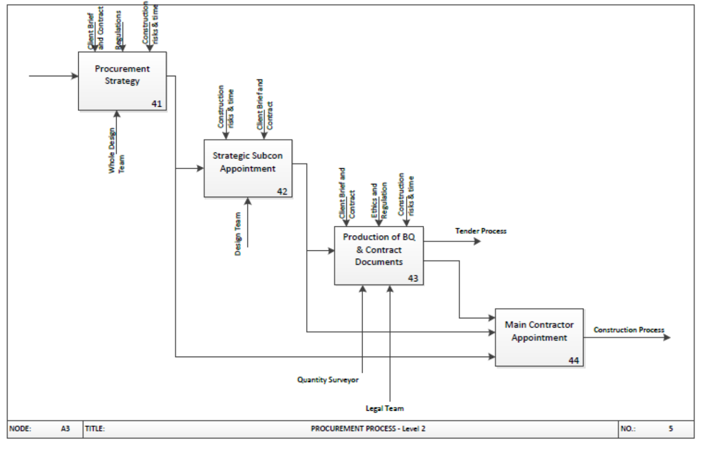
Fig 5. Procurement Process – Level 3 (Source – Author)
The Procurement Process diagram shown in Fig 5 is a child of the Project Development
diagram Fig 2. It outlines the process in deciding the Procurement Strategy. The whole of the
Project Team is required to give their insight and input here.
Given the major constraints of the site, its location and surrounds coupled with the time
constraints of the project the client team decided that it would be a worthwhile risk to enter
into contract with specialist subcontractors before having received a final grant of planning
permission. Michael Green, project director of the Lansdowne Road Stadium Development
Company (LRSDC) stated that the early appointment of the specialist subcontractors “meant
we were ready to start working on site as soon as we had planning permission obtained, it
meant we had a real run at the work”, (Irish Building Magazine, 2011).
This Strategic Subcontractor Appointment paved the way for the production of the full suite
of tender documents as noted in the Production of BQ & Contract Documents. The constraints
have remained the same but at this point the main input comes from the quantity surveying
team and the legal team. Both of these parties are versed in the particulars of the project and
industry and so are best versed to serve the intentions of the client.
The final stage of this process is to appoint the main contractor who will control the physical
construction of the project. Given the size of the project and its associated constraints it will
be necessary to select a contractor capable of completing the project. However, there is a
limited filed of suitable candidates in the Irish market. This is another reason why the whole
project team had such input into the procurement strategy.

Fig 6. Conceptual Design UML (Source – Author)
Marshall (2000), describes Unified Modelling Language (UML) as a tool for specifying,
visualising, constructing and documenting the artefacts of software systems. In this example
a Use case diagram is used to show the conceptual design function of the IDEFO model.
The actor on the left hand side plays the whole design team. This takes into account all
professional parties and the LRSDC. This actor has input into the brief as it develops and then
into concept.
On the right hand side we see some of the controls which will help the concept to develop.
These include the public consultation period, building regulations and the site conditions. The
site conditions take into account limitations which constrain the design namely, location,
existing structure, proximity to a main rail line and environmental risks.

Fig 7. Procurement Strategy UML (Source – Author)
This UML shows how the whole design team, including the LRSDC, design the procurement
strategy for the project. Here we have two actors. The second is the combined quantity
surveying and legal team. This is a secondary function of the strategy.
One of the main factors which drives the whole design team in designing the procurement
strategy is the construction time and risks. These are many and are discussed further in the
following chapters.

Chapter 3 – Task 2 – Detailed articulation of the risk analysis of the pre-construction phase
of the re-development of the Aviva Stadium, Dublin.
“The purpose of a risk register is to record and manage project risks to enable projects to be
delivered successfully” (Corbett and Grigg, 2009).
Every road travelled in life is filled with risk. The same can be said of every venture entered
into including construction projects. Many of the risks noted and analysed in this chapter are
based on presumptions made by the author.
For the purpose of this exercise the author has made presumptions regarding the site and
extent of the risk based on personal knowledge.
In order to rate risk it is advisable to first identify the risks. Some projects have similar risks
but the scoring or impact may be different on a project by project basis based on a range of
criteria.
In order to assign a level of risk (or risk score) we can use a risk matrix. The one that I have
used is an example from Imperial College London.
Fig 8 – Risk Matrix (Imperial College, London)
Risk Scoring Matrix Probability Categories
High/ Critical 3 3 6 9
Prob
Scale
Value
Medium/ Serious 2 2 4 6
H Probable >70% 3
Low/ Marginal 1 1 2 3
M Could happen 30-70% 2
1 2 3
L Improbable <30% 1
Impact Categories
Scale
Value
H Critical 3
M Serious 2
L Marginal 1
Risk Category & Action
Key/ Critical Risks - closely monitor, manage & develop fallback plans
Intermediate Risks - monitor and manage to mitigate/ include specific risk allowances in cost estimate/ programme
Minor Risks - general allowance in base cost estimate & programme
Description
Guide Scenario
Failure that involves significant rew ork, modification or
reassessment
Failure or setback that causes additional work and reassessment
but containable
Probability
Impact has some effect causing rew ork or reassessment but
easily handled
Impact
Description
Low/ Improbable
Medium/ Could happen
High/ Probable

Using a risk register the project team identify project specific risks and assess them using the
risk matrix. The register is used to score the probability or likelihood of a risk occurring and
also what impact the risk will pose to the success of the project.
The author has used an amended version of the risk register from the Imperial College
London. This risk register shows who is responsible for each risk and allows for notation
showing how the risk has been mitigated using corrective actions to date. The author has
made assumptions based on his knowledge of the completed project.
Fig 9 – Risk Register (Imperial College London with Author Amendments)
The risk register does not list the risks in order of priority. As you can see the score allocated
to the probability multiplied by the score allocated to the impact gives the risk score /
category. The risk score is assigned a numeric value whereas the category is assigned a colour
code based on the key provided. A larger version of the risk register shown in Fig 9 is provided
in the appendices.
A. Signing off of the brief - Due to the nature and location of this project the Client did
not sign off the brief fully until they were satisfied that the neighbours and public at
large were satisfied with the project. The locality and its population were very
important factors from conception. Not having the local community onside would
have been detrimental to the success of the planning process. This has been proven
in other high profile planning applications in the area. The impact and probability
KEY: KEY:
Client Client Brief/ User Requirements Key/ Critical
Team
Consultants, Contractors, Suppliers, Procurement Intermediate
External
Town Planning, Third Parties, Statutory Bodies Minor
Design
Consultant/ Contactor Design
Construction
Construction, Logistics, Decanting
Handover
Project Closeout & Handover
Operations
Operations, Maintenance, Facilities Management
Ref
Category /
Responsi
bility
Risk Potential Impact Completed Mitigation Action (to date) Problty. Impact
Risk
Score/
Category
Cost
Impact
(Project
Costs) [£K]
Schedule
Impact
[weeks]
1
Client Signing off of brief can lead to design changes Delay planning and commencement
Public consultation with Client and design team. Early input
from all design team members.
2 2 4
2
External Objections to planning
Project indefinately delayed. Cost for redesign. Client in
contract with specialist sub-contrcators who are aiding with
design.
Transparency in development proceedings and public
consultations. Planning application delayed to allow all
interested parties time to make submissions.
2 3 6
3 Constrcution
Limited site area - proposed development will cover most of the site.
No storage or space for on-site manufacture causing delay
and additional cost.
Investigation into off-site manufacturing solutions and
delivery in a "just-in-time" manner.
3 2 6
4 Construction
Slow deliveries due to poor infastructure around the site Extended construction period and delays
"just-in-time" method of deliveries. Designated drop zones
on site and precise planning.
2 2 4
5
Construction Asbestos in existing stands
Asbestosis to those involved in demolition and in the vacinity
of the works.
Survey carried out. All hazardous materials identified and
removed prior to the mainn demolition works. Air monitoring
as required.
3 1 3
6
Design Damage to rail network crossing site beneath existing stand.
Main Dublin -Wexford passenger and goods rail line being
closed for periods of time.
No works during hours of rail operation in the vacinity of the
works. Any closure of the rail line required will be minimum
and will be programmed in conjunction with Iarnrod Eireann
(State Rail Agency). Prefabricated solution for works to this
area
2 3 6
7
External Injunction due to noise and nuisance Closure of site and delay
Public consultation and agreement with neighbours as to the
extent of the works and preventative measures
2 2 4
8
External Extreme weather conditions Delay and disruption
Extensive site investigation regarding drainage etc.
Proposed start date in May 2007.
1 2 2
9
Design Pollution to local tidal rivers due to demolitiona nd construction waste Remedial clean up operations and cost of same.
Identifcation of rivers etc adjoining the site. Implementation
of waste management system in conjunction with site set
up. Use of sustainable materials.
1 2 2
10
Design
Construction programme over run due to late manufacture and delivery of
components manufactured off-site
Delay to programme and increased costs. Delay and
disruption.
Key off-site manufacturing contractors appointed by client
prior to main tender procurement. Deisgn drawings signed
off during planning
2 3 6
11
Design Unsustainable construction traffic during the early stages of the project Injunction, delay and disruption, additional costs
Recycling protocol in place for demolition waste. Original
sods etc moved to practice pitches.
2 2 4
RISK IDENTIFICATION & MITIGATION
RISK ASSESSMENT - RESIDUAL RISK

were each awarded a score of 3 which contributed to a risk of 9. This shows that the
risk is key / critical. Without this risk being addressed the project may be indefinitely
delayed or may not proceed.
B. Objections to planning – All planning applications stand the risk of objections being
lodged. The risk generally can be defined as being intermediate and as such a minor
stumbling block. However, this project stood the chance of having objections from
private parties and semi state agencies such as Iarnrod Eireann (Rail Agency). As a
result of these possibilities the risk or objection was greater and as such required
mitigation at the early stage of the pre planning application stage. This was done by
the Client team being very transparent in its dealings by using public meetings and by
consulting with all relevant parties. This prolonged the preparation of the planning
application but mitigated the risk of serious objections.
C. Limited site area - Proposed development will cover most of the site - The limited site
area reduced the space available for onsite fabrication. If not addressed this may lead
to a delay in the construction programme, additional preliminaries and supervision
costs. It was decided by the design team to investigate various forms of off-site
construction coupled with traditional methods of construction. A construction
programme using a “just-in-time” delivery method was also investigated to mitigate
the risk and its impact.
D. Slow deliveries due to poor infrastructure around the site – At planning stage the
need for “just-in-time” deliveries was noted as a solution to risk 2. However, it was
also noted that traditional construction methods on large scale projects generally
tend to lead to increased levels of traffic. This concern was intensified by the need for
additional deliveries due to the volume of proposed off-site manufacture and
associated deliveries. The locality in which the project is situated is a well-developed
residential and high profile area with no room for the widening of roads and no
provision for off street parking of lorries or trailers. This risk is in the intermediate
category and can be mitigated using good construction and logistics planning.
E. Asbestos in existing stands - The construction of the existing stands visibly contained
asbestos and as a result also posed a risk. The author has determined this to be a
medium risk as the materials used contained minimal amounts of asbestos to
constitute a high risk. The risk is still present but as the materials were not damaged,

the author has determined this to be an intermediate risk. In order to mitigate this
risk a survey will be carried out in order to identify the extent of the issue and
categorise the various risks so as to allow for the safe removal and disposal of same
prior to the completion of the demolition works.
F. Damage to rail network crossing beneath existing stand – The main Dublin to Wexford
rail line runs at the base of one of the stands and crosses the site. This adds further
limitations to the actual working area of the site as noted in earlier risks. However the
proposed structure will actually be partially built over the rail line. The realignment of
the rail line is not an option. It is also not an option to divert rail traffic from the area
as the Irish rail network is limited compared to other European countries. The author
has assumed a medium probability of the risk occurring due to the author’s
experience of working in proximity to rail networks. The level of training, regulation
and safety precautions in place for working on or next to rail lines is defined in
Railways Safety Act 2005 and guidelines for third parties are provided by Irish Rail,
(www.irishrail.ie). Also the rail line in question does not operate on a 24 hour basis
and so work can be scheduled around these periods. However in the event of an
incident occurring, it would be detrimental to the project and so the risk is critical to
the success of the project. This risk was mitigated by scheduling the works in the area
outside of peak rail usage times and by minimising the amount of rail closures
required. The use of offsite prefabrication was of huge importance here. The rail line
was protected by a pre-cast concrete tunnel which was designed as part of the
planning process in conjunction with the rail agency. This was only possible by the
involvement of the whole design team and the early involvement of the specialist
subcontractors, in this case. This is further confirmed by comments made by Mr.
Green of the LRSDC in the Irish Building Magazine’s article on the Aviva in 2011.
Fig 10 (Below) Precast tunnel in place above rail network. The new stand is built
around this structure.

G. Injunction due to noise and nuisance – The local residents and community groups had
previously campaigned vigorously against the redevelopment of the stadium and its
facilities. The stadium is situated in a very affluent suburb of the city and so the
funding of any opposition was not to be an issue. Any such injunction or threat thereof
would have had an adverse effect on the project. It would have caused both time
delay and cost issues. The LRSDC made the whole team aware of this at the early
stages and it was decided to conduct public consultation and meet with the
representative of the groups concerned. Whilst noise and dust are inevitable in all
construction projects it must be taken into account that some projects are more
sensitive than others. The threat of injunction on this project would not have been a
one off occurrence and so it was necessary to mitigate the risk as early as possible.
The author presumes that the appointment of a project / community liaison
representative or team was key to reducing the risk. This would have allowed a clear
line of communication between the al parties concerned.
H. Extreme weather conditions – This is viewed as a low risk due to the way in which the
design developed and the construction methods used. The project still contained
factors which needed to be addressed under this heading such as the demolition and

ground works packages. Excessive rain and wind here would have caused delay which
would have had a time and cost implications. The site is situated with a few miles of
the coast and so was susceptible to intermittent high winds, but no more than other
sites in the capital. The author believes that in order to mitigate this risk extensive
site investigation works are required to expose area which may be prone to delay due
to rain or a rise in the ground water levels. The main mitigating factor is the scheduling
of work which can be affected by seasonal weather changes to be scheduled for
commencement during periods of relative calm. This information can be accessed
through meteorological data.
I. Pollution to local tidal rivers due to construction and demolition waste – Most of
Dublin city and its suburbs is built on reclaimed land. This reclamation started during
the Vikings time in Ireland as noted by Simms (1979). As a result there are numerous
rivers and underground streams running through the city to the sea at Dublin Bay.
One such river, The Dodder, flows close to the site of the Aviva stadium and has many
underground tributaries which cross the site. It is necessary to form culverts around
these waterways in order to protect both them and prevent flooding to the
development. The waterways beneath the development were encased using precast
concrete culverts early in the development. This use of precast culverts reduced the
risk of construction waste for this process entering the waterways. The fact that the
waterways where encased early in the project reduced the risk of any contamination
either intentional or unintentional. These measures were decided on in the design
and procurement stages.
J. Construction programme overrun due to late manufacture and delivery of
components manufactured off-site - A noted in the Chapter 2 diagrams, the whole
design team reviewed the planning from first principles in line with the Client brief
and in conjunction with public consultation. This approach led to the need for early
and strategic appointment of specialist subcontractors. These sub-contractors had a
dramatic input into the design of major elements of the structure. The sub-
contractors needed to be chosen based on their ability to design, manufacture and
deliver. The main contractor also had a large part in the programming of the works in
this regard. A failure on either party’s part would have led to delays. These delays
would have had significant time and cost delays, not to mention the risk of dispute.

The early appointment and involvement of these subcontractors allowed for designs
to be completed and signed off by the Client team before the main contractor was
appointed. Site investigations were concluded well in advance and when the project
had received planning permission the specialist subcontractors were in a position to
organise their production lines as well as their construction teams. This was
invaluable. Now the construction team needed to incorporate this information into
the construction programme and ensure that the logistical issues noted earlier were
resolved.
Fig 11 – (Below) Specialist Subcontractor screenshot showing steel frame at
preconstruction stage. (Source – Populous)
K. Unsustainable construction traffic at the early stages of the project – At the early
stages of this project it will be necessary to demolish the existing stand, establish the
site and complete the ground works as noted earlier. Traditionally this would mean a
line of trucks being loaded and disposing of materials. Traffic is constant around the
site due to its location and given that the construction of the project commenced
towards the end of Ireland’s last property boom the construction traffic in the city
was already a concern. This could have led to injunctions and delays to programme

and cost implications. In order to mitigate the risk recycling protocols were put in
place which reduced the traffic and also aided in the sustainable construction of
elements of the building. However this did add to the restriction of the working area
of the site and was another factor which helped to define which components to the
structure needed to be manufactured offsite.
Fig 12 (Below) Demolition of the East stand at the original Lansdowne road stadium.
(Source – www.Flickr.com)

Chapter 4 – Task 3
Offsite Construction
Due to the time constraints mentioned in earlier chapters it is easy to understand how
elements of offsite construction were necessary in order to complete the project to the
client’s requirements and within the required time frame.
Studies in the United Kingdom have noted that the use of offsite construction methods in
larges housing developments is low. The current usage looks set to increase due to the need
“to improve quality, cost, time, productivity and health & safety” (Pan, Gibb & Dainty, 2008).
With regard to general construction projects, Alvanchi et al (2012), note that the planning of
offsite production of construction components can provide more challenges than solutions to
the construction manager. The authors further discuss the use of discrete event simulation
to reduce the challenges. During the design and construction of Aviva Stadium elements of 3
dimensional (3D) designs was used to help to ease the planning process.
Early in the planning and design elements of this project the all design team members realised
the need for working to the main constraints of the project namely, time and onsite
manufacturing facilities. Another issue which was realised is that components manufactured
in factory settings provide higher and more consistent levels of quality than those
manufactured onsite. However, more planning is required with offsite manufacturing than
with onsite construction. Offsite manufacture requires more forward planning than other
methods of construction due to the many different types of off-site construction options
available.

Fig 13 – Types of Off-site construction.
As shown in Fig 13 there are 3 main classifications of off-site construction and these are
Non-volumetric pre-assembly – This comprises of units which do not create a
usable space in their own rights but are connected to the building frame
irrespective of the construction. An example of this is a prefinished wall panel.
Volumetric pre-assembly – Here a pre-assembled factory finished unit is
produced which creates a usable space. An example of this is toilet pod.
Modular building – Here the preassembled volumetric units referred to above
actually form the building as a whole. The main assembly of each of the units
to form the structure is completed onsite.
The redevelopment of the Aviva Stadium in Dublin had many constraints in relation to its
construction. As noted in earlier chapters these constraints were overcome by appointing the
specialist subcontractors at the planning stage. This enabled the whole design team to
evaluate the use of different methods of construction prior to the planning stage let alone at
tender and pre-appointment of the main contractor.
Precast concrete solutions were used for forming culverts for naturally occurring waterways
within the site and a protective tunnel for the rail network running through the site. These
were prefinished units which could be defined as being within the volumetric pre-assembly

category as they provided a usable space. It is the opinion of the author that the definition of
the usable space is dependant of the function which the structure will fulfil. This function will
change from project to project and differs between building and civils projects.
These solutions mitigated risks as noted in the risk register which may have caused delay and
cost implications. The use of the precast solution around the rail network saved time and cost
as well as disruption to the rail network. The precast solution was designed, manufactured
and brought to site on a just-in-time manner. The use of this solution reduced disruption of
the rail network to a minimum. It was only necessary to close the rail line for a 72 hour period
in order to complete the main installation. This was carried out over a bank holiday weekend
with bus transfers in place to provide alternative travel arrangements.
Other precast concrete solutions were also incorporated into the structure. These include
elements of the structural frame, floor slabs and stairs. These items on their own do not
provide a volumetric solution but would be considered to be part of the non-volumetric pre-
assembly. The use of the these forms of construction allowed the building to progress at a
more progressive rate than if only traditional in-situ methods had been used.
Fig 14 - Precast Concrete frame construction (source: www.patkirwan.ie)
PM Group’s Pat Molloy is quoted as saying “The extensive use of precast concrete elements
had the additional benefit of providing a cleaner, whiter finish”, (Irish Building Magazine,
2011).
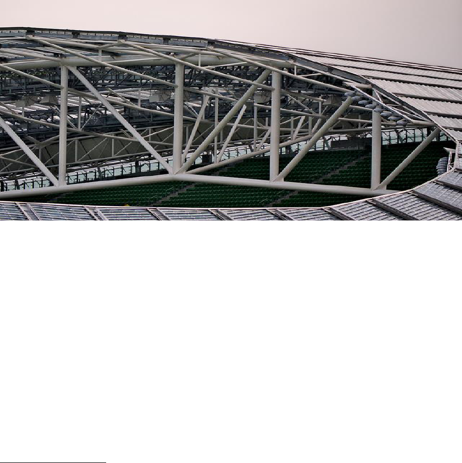
Fig 15 – Roof steel on the Aviva Stadium (Source: www.flickr.com)
The steel frame for the external wall and roof cladding is another example of modular
construction on this project. Again Pat Molly refers to off-site manufacture as being a key
issue in this regard. Apart from the early design and off-site manufacture the installation of
the roof steel work in particular benefited from the use of bolted rather than welded joints.
This is a key feature of this well designed off-site manufactured solution. It saved cost and
time in construction as well as allowing for a just-in-time delivery process.
Quality Management
It is quite usual in the Irish construction industry for contractors to be asked to provide
evidence of quality management certification or evidence of systems they have in place when
completing pre-qualification questionnaires. Generally an answer in the affirmative signifies
that the contractor has some form of document management systems in place. But is this
enough to guarantee quality?
In real terms the short answer is no, not entirely. However, a document management system
does provide a paper trail which can be used as part of a quality control system in the
construction process.
A paper trail system such as ISO: 9001 can be used to link many functions within an
organisation, make processes more streamlined and prevent duplication of work. If we look
at the process of the manufacture of a precast floor slab we can look at how a paper based
quality management system work.
Design – Slab engineered and designed to meet client brief. The initial design and
specification is reviewed and once correct signed off for issue for construction.
Tender – The drawings and specification for the slab is now issued for pricing.
Manufacture – The appointed contractor now has a specification and drawings which
specify how the slab is to be made, the materials required, the finish required and all
tolerances. And special requirements. This specification allows the manufacturing
team to examine the slab and determine if it meets the specification.
Delivery to site – Once the slab is delivered it will be check for defects by the
construction team prior to installation.
The stages noted above are just overviews and do not look deeper at the review and
examination of the many components of each stage.
In relation to the Aviva Stadium project it was very important to have a quality management
system in place. Given the size and complexity of the project the system required would need
to have many tiers and be adaptable to all processes within the project.
In relation to this project I believe the pre-planning process used was a variant of Business
Process Reengineering (BRP). Harmon (2003, chp. 9) describes a comprehensive generic
methodology consisting of five phases as outlined below:
1. Planning a process design effort
2. Analysis of an existing process
3. Design of a new or improved process
4. Development of resources for an improved process
5. Managing the implementation of the process
With regard to the Aviva Stadium project the first phase consisted of the formation of the
project team and its key players. The second was a review of the traditional pre-planning and
procurement mechanisms. The third was the design of the new strategy which incorporated
early engagement of the many design team members and specialist subcontractors and the
decision to engage new construction techniques and mechanisms. The fourth was the review
of resources required for the process. These resources include mechanisms for design,
manufacture, delivery and installation. The fifth, the author assumes, was the formulation of
management structures for the control of quality management.
The author believes that the BRP methodology can be used in many different sectors on many
industries with success.
Chapter 5 – Conclusions and Recommendations
Every construction project is different. The Aviva Stadium redevelopment is a very unique
structure and had many different issues which required meticulous planning and execution.
The client was well aware of the many problems which could arise in relation to the planning
of the project but was willing to acknowledge that the only way to proceed in an efficient
manner was to employ a team of expert construction professionals from the earliest point
possible.
The project process as outlined in the Irish Building Magazine (2011) shows how a multi-
disciplinary team, including specialist subcontractors, working together could re-engineer the
planning and construction process in a manner which saved more than a year from
programme. Whilst the design of the building could have been achieved using traditional
construction methods the consistency of the quality of the finishes may not have been
achieved.
The main recommendations that the author would make are:
1. The clients should take council from there professional team and plan their projects
correctly and in a timely manner.
2. The whole project team should define the processes to be used in the construction
and evaluate the benefit of alternative methods of construction and the possible
benefits which may be derived from their use.
The author was impressed by the manner in which the planning stage was approached by the
client and the design team. The use of strategic subcontractors early in the design and
procurement process was ingenious.

Chapter 6 – References
Alvanchi, A., Azimi, R., Lee, S., AbouRizk, S. M., & Zubick, P. (2011). Off-site construction
planning using discrete event simulation. Journal of Architectural Engineering, 18(2), 114-122.
Aviva Stadium Facts (n.d). Retrieved 12 March, 2014, from
http://www.avivastadium.ie/.../download-the-aviva-stadium-fact-sheet-here-.pdf?
Corbett, P., Grigg, W. (2009). Risk Registers in Construction: Theory with Practice. Retrieved
from http://www.ascpro0.ascweb.org/archives/cd/2009/paper/CPGT94002009.pdf
Harmon, P. (2003). Business process change: a manager's guide to improving, redesigning,
and automating processes. Morgan Kaufmann.
Imperial College London, Example Risk Register (n.d). Retrieved 2
nd
April 2014, from
www.imperial.ac.uk/.../exampledocs/1.20RiskRegisterexample.xls
Irish Building Magazine (December 14, 2011). Retrieved 4
th
March 2014, from
http://www.irishbuildingmagazine.ie/2011/12/14/the-aviva-stadium.
Irish Rail, Guidance for Third Party Works (n.d), Retrieved 10
th
March 2014, from
http://www.irishrail.ie/about-us/third-party-works.
Marshall, C. (2000). Enterprise modelling with UML: designing successful software through
business analysis. Addison-Wesley Professional.
Pan, W., Gibb, A. G., & Dainty, A. R. (2008). Leading UK house builders' utilization of offsite
construction methods. Building Research & Information, 36(1), 56-67.
Simms, A. (1979). Medieval Dublin: a topographical analysis. Irish Geography, 12(1), 25-41.
Chapter 7 – Appendices

IDEFO Diagrams
TITLE:NODE: NO.: 1A-0 AVIVA STADIUM (Context) - Level 0
0
A0
Planning and design of new Aviva stadium
Building regulations.
Client requirements.
Planning Conditions
Exiting structures
and site
Finalised
construction plans
for procurement
and construction
Architects,
Engineers,
Construction
Managers,
Planners.
Quantity
Surveyors
Issues: Location,
Neighbours,
Restricted
working hours
Project idea –
State of the art
facility for
provincial and
international
rugby and soccer.
Alternative uses
as a conference
centre and
concert venue.

TITLE:NODE: NO.: 2AO Project Development - Level 1
1
Project Inception
2
A1
Planning
2
A2
Design
4
A3
Procurement
5
Construct
6
Operate and
maintain
1
2
3
2
2
Site conditions
and environment
Regulations
Resources
Project Idea
Project Champion
Client Brief
Contract
Documents
Site conditions
and environment
Planning team
Client Brief and
contract
Regulations
Site conditions and
environment
Design team
Client Brief and
contract
Regulations
Construction risks
& time
Cost Control Team
Client Brief and
contract
Regulations
Construction Plan
Client Brief
Contract
Documentation
Management
Plan
Construction Team
Maintenance Team
1) Client Brief
2) Performance Information and
Project Knowledge
3)Construction and
Maintenance Plan
Project Evaluation
Project and Site Information
Project and Planning Knowledge
Overview of Procurement (Contractor and sub-contractor)
Design Documents
Project and Site Information
Project Technical Specification
Tendering
Appointment of Main Contractor
Special conditions
Post construction documents
Completed project
Construction Knowledge
Operational structure
Maintenance Knowledge
Performance Information

TITLE:NODE: NO.: 3A1 Planning Process - Level 2
21
Conceptual design
planning
22
Construction
Planning
23
Estimating Cost
24
Document
Production
Design team
3D & 4D Modelling Software
Project Management
Team with Specialist
Sub-contractor input.
(MS Project)
Public
Consultation
Estimating Team
including
specialist sub-
contract teams
(BT2 / CostX)
Whole team
(Ms Office)
Building Regs
Client Brief
Site
Conditions
Client Brief
Site
Conditions
Construction Methods
Client Brief
Resources
available
SCSI
Standards
Client Brief
Contract
Documents
Site Conditions and
Environments
Resources
available
Approx. Bills of materials
Approx. Bills of Quantities
Conceptual design specifications
Input from public bodies and individuals
Production Programme
Materials and component assembly
Labour / plant etc estimation
Material cost estimation
Direct and indirect cost estimation
Cost of components and assembly estimate
Project Plans
Specifications
Project and site information
Method of procurement

TITLE:NODE: NO.: 4A2 DESIGN PROCESS - Level 2
31
Conceptual design
32
Tender Design
33
Detailed Design
Building Regs
Client Brief
Site
Conditions
Planning
Whole Team
Specialist
Subcontractor
Design Team
Public
Consultation
Procurement
Specialist
Subcontractor
Whole Team
Service Provider
Building Regs
Client Brief
Site
Conditions
Site Conditions
Client Brief
Building Regs
Project Inception
Procurement

UMLDiagrams


Risk Scoring Matrix Probability Categories
High/ Critical 3 3 6 9
Prob
Scale
Value
Medium/ Serious 2 2 4 6
H Probable >70% 3
Low/ Marginal 1 1 2 3
M Could happen 30-70% 2
1 2 3
L Improbable <30% 1
Impact Categories
Scale
Value
H Critical 3
M Serious 2
L Marginal 1
Risk Category & Action
Key/ Critical Risks - closely monitor, manage & develop fallback plans
Intermediate Risks - monitor and manage to mitigate/ include specific risk allowances in cost estimate/ programme
Minor Risks - general allowance in base cost estimate & programme
Description
Guide Scenario
Failure that involves significant rew ork, modification or
reassessment
Failure or setback that causes additional work and reassessment
but containable
Probability
Impact has some effect causing rew ork or reassessment but
easily handled
Impact
Description
Low/ Improbable
Medium/ Could happen
High/ Probable

RISK SCORING MATRIX (Imperial College London)
RISK REGISTER – Imperial College London ( – Amended)
KEY: KEY:
Client Client Brief/ User Requirements Key/ Critical
Team
Consultants, Contractors, Suppliers, Procurement Intermediate
External
Town Planning, Third Parties, Statutory Bodies Minor
Design
Consultant/ Contactor Design
Construction
Construction, Logistics, Decanting
Handover
Project Closeout & Handover
Operations
Operations, Maintenance, Facilities Management
Ref
Category /
Responsi
bility
Risk Potential Impact Completed Mitigation Action (to date) Problty. Impact
Risk
Score/
Category
Cost
Impact
(Project
Costs) [£K]
Schedule
Impact
[weeks]
1
Client Signing off of brief can lead to design changes Delay planning and commencement
Public consultation with Client and design team. Early input
from all design team members.
2 2 4
2
External Objections to planning
Project indefinately delayed. Cost for redesign. Client in
contract with specialist sub-contrcators who are aiding with
design.
Transparency in development proceedings and public
consultations. Planning application delayed to allow all
interested parties time to make submissions.
2 3 6
3 Constrcution
Limited site area - proposed development will cover most of the site.
No storage or space for on-site manufacture causing delay
and additional cost.
Investigation into off-site manufacturing solutions and
delivery in a "just-in-time" manner.
3 2 6
4 Construction
Slow deliveries due to poor infastructure around the site Extended construction period and delays
"just-in-time" method of deliveries. Designated drop zones
on site and precise planning.
2 2 4
5
Construction Asbestos in existing stands
Asbestosis to those involved in demolition and in the vacinity
of the works.
Survey carried out. All hazardous materials identified and
removed prior to the mainn demolition works. Air monitoring
as required.
3 1 3
6
Design Damage to rail network crossing site beneath existing stand.
Main Dublin -Wexford passenger and goods rail line being
closed for periods of time.
No works during hours of rail operation in the vacinity of the
works. Any closure of the rail line required will be minimum
and will be programmed in conjunction with Iarnrod Eireann
(State Rail Agency). Prefabricated solution for works to this
area
2 3 6
7
External Injunction due to noise and nuisance Closure of site and delay
Public consultation and agreement with neighbours as to the
extent of the works and preventative measures
2 2 4
8
External Extreme weather conditions Delay and disruption
Extensive site investigation regarding drainage etc.
Proposed start date in May 2007.
1 2 2
9
Design Pollution to local tidal rivers due to demolitiona nd construction waste Remedial clean up operations and cost of same.
Identifcation of rivers etc adjoining the site. Implementation
of waste management system in conjunction with site set
up. Use of sustainable materials.
1 2 2
10
Design
Construction programme over run due to late manufacture and delivery of
components manufactured off-site
Delay to programme and increased costs. Delay and
disruption.
Key off-site manufacturing contractors appointed by client
prior to main tender procurement. Deisgn drawings signed
off during planning
2 3 6
11
Design Unsustainable construction traffic during the early stages of the project Injunction, delay and disruption, additional costs
Recycling protocol in place for demolition waste. Original
sods etc moved to practice pitches.
2 2 4
RISK IDENTIFICATION & MITIGATION
RISK ASSESSMENT - RESIDUAL RISK
