
1
1/13/2021
Table of Contents
Chapter 1 Introduction ................................................................................................................................................. 3
1.1 Preface ................................................................................................................................................................ 3
1.2 Safety .................................................................................................................................................................. 3
Power Supply ........................................................................................................................................................ 3
Chapter 2 Specifications ............................................................................................................................................... 4
Chapter 3 Main Parts & Assemblies ............................................................................................................................. 5
Chapter 4 Installation ................................................................................................................................................... 7
4.1 Unboxing and Inspection .................................................................................................................................... 7
4.2 Machine Assembly .............................................................................................................................................. 8
4.2.1 Outfeed Tray and Card Catcher ................................................................................................................... 8
4.2.2 Extension Table Installation ......................................................................................................................... 8
4.2.3 Power Socket and Switch ............................................................................................................................. 8
Chapter 5 Operation ..................................................................................................................................................... 9
5.1 Key Panel Introduction ....................................................................................................................................... 9
5.2 Quick Start ........................................................................................................................................................ 10
5.3 Screen ............................................................................................................................................................... 10
5.3.1 Welcome Screen ........................................................................................................................................ 10
5.3.2 Ready Screen.............................................................................................................................................. 10
5.3.3 Mode Introduction ..................................................................................................................................... 12
5.3.4 Smart Input Mode ...................................................................................................................................... 16
5.3.5 Job Layout Creation ................................................................................................................................... 18
5.3.6 Parameters ................................................................................................................................................. 18
5.3.7 Job Layout Parameters .............................................................................................................................. 19
5.3.8 How to Create a Register Mark .................................................................................................................. 23
5.3.9 How to use a Register Mark ....................................................................................................................... 24
5.3.10 Using the Cut Mark Registration .............................................................................................................. 24
5.4 Hardware Setting .............................................................................................................................................. 25
5.4.1 Side Guide Setting ...................................................................................................................................... 25
5.4.2 Positioning Slitters ..................................................................................................................................... 25
5.4.3 Skew Adjustment ....................................................................................................................................... 26
5.4.4 Outfeed Tray Setting .................................................................................................................................. 27
2
5.5 Slitters Setting ................................................................................................................................................... 28
5.5.1 Compensation for Image Shift Left/Right .................................................................................................. 29
5.5.2 Side Trimming ............................................................................................................................................ 30
5.5.3 Paper Deflectors ........................................................................................................................................ 31
5.5.4 Set Crease Data .......................................................................................................................................... 31
5.6 Side-Sheet Trimming ......................................................................................................................................... 31
5.6.1 Slitter Placement ........................................................................................................................................ 31
5.6.2 Set Cut Data ............................................................................................................................................... 32
5.7 Slide-in Tools ..................................................................................................................................................... 32
5.7.1 Change Perforate Crash Pad ...................................................................................................................... 33
5.7.2 Crease Depth Adjustment .......................................................................................................................... 34
5.8 Slitter Removal and Replacement .................................................................................................................... 35
5.9 Slitter Blade Removal Procedure ...................................................................................................................... 37
Chapter 6 Trouble Shooting ........................................................................................................................................ 39
6.1 Error and Warning Codes .................................................................................................................................. 39
6.1.1 Warning...................................................................................................................................................... 39
6.1.2 Error ........................................................................................................................................................... 41
6.2 Image Compensation ........................................................................................................................................ 42
Chapter 7 Maintenance .............................................................................................................................................. 43
3
Chapter 1 Introduction
1.1 Preface
This manual only applies to the PT 331SCC. This manual contains information regarding machine safety and use.
Please keep the manual on hand for easy access when required. Do not operate the Graphic Whizard PT 331SCC
until you read and understand the instructions in this manual. Any questions regarding this machine, please contact
Graphic Whizard.
Graphic Whizard pursues a policy of continuing improvement in design and performance of the product.
Therefore, the product design and specifications are subject to change without notice.
1.2 Safety
• Please shut down and disconnect the power to the machine before performing maintenance. Make note
of connections before disconnecting. Ensure all cables are properly secured to the board.
• Read this entire manual before running the machine.
• Ensure all accessories are installed properly before running the machine.
• Ensure the power input and ground are correct before powering on the PT 331SCC. This machine runs on
110 volts
• Ensure all safety covers are in place. Do not run the PT 331SCC without the covers installed. The top cover
has an interlock switch that will stop the machine if open or removed.
• For personal safety, disconnect power before cleaning the interior of the machine.
• The blade edges are very sharp. Use caution whenever accessing the interior of the unit.
• Disconnect the power cord if the machine will not be used for an extended period.
• Install the PT 331SCC on a level surface.
• Never operate the unit with wet hands or connect or disconnect the power cord when wet or when
standing in water.
• Keep hair and clothing away from the unit.
• Keep hands clear of the unit when operating. Keep liquids away from the PT 331SCC.
• Do not place any heavy material on the machine.
• To avoid risk of shock or fire, keep metal and flammable materials out of the machine. If the unit is
exposed to shock or fire and if it is safe to do so, power off and unplug the unit then call a service
technician. Do not power on the unit without consulting a service technician.
• If the machine overheats or if you detect an odor or see smoke, immediately shut down the unit and
contact your local service technician.
Power Supply
• The AC input voltage frequency is AC110/50-60Hz. Please use a power cord rated for 10A or higher.
• If the voltage or frequency is not within range, the machine may fail to function.
• Do not remove the power cord while machine is in use. Power down the PT 331SCC before disconnecting
the power cord.
• Ensure the unit is connected to a properly grounded outlet before powering on.

4
Chapter 2 Specifications
Item
Parameter
Package Dimensions
Length*Width*Height (inch) (mm)
52.36” x 22.44” x 38.5”
(1330 x 570 x 980mm)
Machine Dimensions
Length*Width*Height (inch) (mm)
26.38” x 24.80” x 45.28”
(670 x 630 x 1150mm)
Net Weight
KG / LBS
100kg / 220 lbs.
Package Weight
KG / LBS
116kg / 255 lbs.
Power
Input
AC110V, 50/60Hz, 150W
Output Size
Max (W*L) (inch) (mm)
12.52” x 25.50” (318 × 640mm)
Min (W*L) (inch) (mm)
2.17” x 1.89” (55 × 48mm)
Infeed Size
Max (W*L) (inch) (mm)
13” x 25.5” (297 × 650mm)
Min (W*L) (inch) (mm)
6.5” x 8.27” (210 × 210mm)
Thickness
0.006” - 0.014”
150g - 350gsm / 0.15 - 0.35mm
Paper Waviness
0.118” (±3mm)
Max Qty for Cutter per Sheet
32
Accuracy for Cutting
±0.008” - 0.016” (0.2 - 0.4mm)
First Cut
0.126” - 0.591” (3.2 - 15mm)
Last Cut
0.197” - 0.591” (5 - 15mm)
Gutter Cut
0.118” - 0.591” (3 - 15mm)
Slit
Slitters
4
Side Trim
3.2mm-10mm (0.126” – 0.375”)
15mm or greater
Gutter Slit
0.375” (10mm)
Accuracy for Slitting
±0.0118” (0.3mm)
Crease
Max Qty for Crease per Sheet
32
Crease Depth Adjustment
Infinite Manual Adjustment
Crease Direction
Both
Crease Die Spec.
1.0mm
Perforator
Perforate Die Spec.
12 TPI
Speed
A4 trimming 4 sides, crease in middle
20 sheets/min
Feeding
Middle Infeed
Hand Feed
Custom Memory Storage
20
Register Mark
Y Direction only
Image Compensation
Y Direction Compensation Only
Environment
Temperature
10°C to 35°C / 50°F to 95°F
Humidity
30% to 70%

5
Chapter 3 Main Parts & Assemblies
No.
Item
Description
1
Waste Bin
Catches the cut waste
2
Out Feed Tray
For longer cut crease jobs
3
Card Collector
Collect finished business cards
4
Top Cover
Protection
5
Keypad
Machine programming and operation
6
Feed Table
Paper input
7
Machine Body
Working body of the PT331SCC
8
Side Cover
Access panel for changing the crease die or
perforate die
9
Tools Storage
Holder for crease and perf tools
10
Stand
Holds the waste bin and tool accessories

6
No.
Description
Remark
1
Crease Depth Adjust Screw
Turn clockwise to lighten the depth, counterclockwise to deepen the
depth.
2
Cross Cutter
Cut paper in cross direction
3
Lag Wheel Set
Adjust the roller pressure
4
Slitter #1
Slit the side edge of paper
5
Slitter #2
Slit with fixed gutter, gutter is 8mm or 3/8”
6
Slitter #3
Slit with fixed gutter, gutter is 8mm or 3/8”
7
Slitter #4
Slit the other side edge of paper
8
Manual Side to Side
Adjustment
Adjust slitter side to side positions

7
Chapter 4 Installation
4.1 Unboxing and Inspection
• Check for any obvious damage as soon as the item is received.
• If the package is damaged, perform a visual inspection before uncrating the PT331. Document any marks
or dents with pictures.
• If there is no visible damage, open the package and use the packing checklist to check for any missing or
broken parts. If there is any visible damage or parts that are missing, please take pictures and notify
Graphic Whizard immediately.

8
4.2 Machine Assembly
4.2.1 Outfeed Tray and Card Catcher
The card catcher is designed to sit just behind the exit rollers, allowing the cards to fall freely from the machine.
Use the deflectors to help guide the cut stock.
4.2.2 Extension Table Installation
Attach the feed extension table to the PT 331SCC by loosening the three hex screws and slipping the tray over the
screws. Ensure the tray remains level when tightening the screws.
4.2.3 Power Socket and Switch
AC input, voltage/frequency is 110V/50-60Hz. Note: For machine and operator safety, there is a fuse in the power
inlet. If the machine does not power on when connected to a functioning 110V power outlet, check the fuse.

9
Chapter 5 Operation
5.1 Key Panel Introduction
The control panel consists of keys and screen, as per following picture:
No.
Key
Description
1
Stop
Stops the current job.
2
Start
Runs the current job.
3
Test
Runs a single sheet for testing purposes.
4
Clear
Clears the data or error.
5
Number Pad
Used to input job data.
6
Scroll
Advance to the next option.
7
Indicator- No Paper
No paper or infeed Jam error indicator.
8
Indicator- Motor Error
E-1 CR Motor Error. Indicates a crease motor lock error.
9
Indicator- Paper Jammed
C-2 Jam at in feed error or C-3 Jam at out feed error (see display). Paper
jam error.
10
Indicator- Safety Cover
C-1 CR cover open. Safety cover is open.
11
Forward/Reverse
Increase/Decrease
Used to clear jams. Whenever possible, move the paper towards the
outfeed rollers.
12
Mode
Change the modes
13
Screen
Display information.
14
Enter
Press enter to confirm changes.

10
5.2 Quick Start
1. Power on the PT331SCC.
2. Select a preset template option from Mode or create a new template by following the procedure detailed
in 5.3.3
3. Add paper and adjust the side guides to secure the stock. The guides move towards the center of the
machine (center justified).
4. Ensure the output tray is installed. If cutting business cards, add the card catcher and deflectors.
5. Run a test cut by pressing the test key. Check alignment and skew. If the paper is skewed, adjust the side
guides referred to in section 5.4.2.
6. If the finished pieces are not OK, use the compensation function to make the appropriate adjustments.
7. Once the cut and adjustments are set, press Start to run the job. You can input the quantity you would
like to cut by entering the number and pressing the Enter key before pressing Start. If you are not using
the Batch function, press Stop once the desired number of sheets have been cut.
5.3 Screen
5.3.1 Welcome Screen
When you first power on the PT 331SCC, the screen will show a welcome message, then go to the Ready Screen.
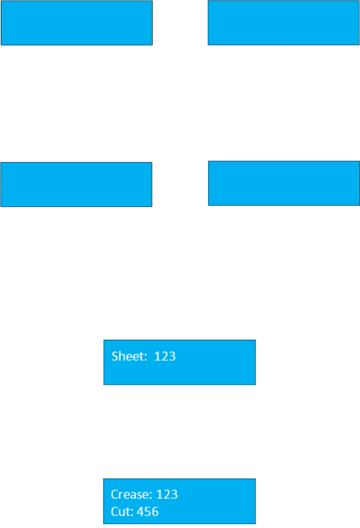
5.3.2 Ready Screen
From the ready screen, press the Page down key to scroll through the various options. There are five options
from the ready screen:
• Cut data
• Crease data
• Total sheets
• Crease and cut quantity
• Software version
Main Screen Ready Status
11
Cut Data Screen
The data cut screen shows the currently programmed cuts. If no cuts have been programmed, the values will
display as 0. The maximum number of programmable cuts is 32. To page through the programmed cuts, press the
Up or Down arrows on the keypad (page up / page down).
Crease Data Screen
Like the cut data screen, the crease data screen displays the programmed creases. A total of 32 creases can be
programmed. To view the programmed creases, press the Down key.
Total Sheets Screen
The totals screen can be accessed by pressing the Up or Down arrow on the keypad from the main screen. The
total sheet screen displays the total number of sheets run. It will not count sheets jammed when the machine
experiences an error or warning.
Total Crease and Cut Quantity Screen
The total crease and cut quantity screen display a count of the total number of creases and cuts.
2
1)
4
2)
6
3)
4)
8
29) 0
30) 0
31) 0
32) 0
2
1)
4
2)
6
3)
4)
8
29) 0
30) 0
31) 0
32) 0

12
Software Version & Serial Number
When calling Graphic Whizard for warranty replacement or troubleshooting, you must provide the Graphic
Wizard serial number, located on the machine near the power on button. It may also be necessary to provide the
manufacturer serial number and software version. Please have the Graphic Whizard machine serial number,
software version, total cut and crease count, and the totals count available.
5.3.3 Mode Introduction
To view the available programming options and to input data, press the Mode button. Pressing the Stop Key
will return you to the Ready screen if you have not made any changes.
The following is a list of available options:
Recall Job
The PT 331SCC can save a total of 20 jobs. Each job is saved under a number
(starting at 1). To recall a job, key in the number that corresponds to the
required job on the number pad and press the enter button.
Factory Template
The PT 331SCC comes preloaded with preset templates. The template parameters are as follows:
• 3.5” x 2”
• 3.5” x 5”
• 3.5” x 8“
• 5” x 8”
• 5” x 8.5”
• 5.5” x 8”
• 5.5” x 8.5”
To access the templates, press the Mode Key once to enter factory template screen. Press the Page Up Key or the
Page Down Key to scroll through the preset templates. Press the Enter Key to select the desired template. When
using the factory templates, set the slitter positioning gauge to match the width of the finished job (3.5” or 5.5”).
M
Recall Job
Job No. 1

13
Set Paper Length
The Input the paper sheet length is the length of the sheet before it has been
trimmed. The maximum length the PT 331SCC can process is 25.5”. There is
no need to set the sheet width.
Register Mark Function
The PT 331SCC is equipped with a register mark reader. To activate the reader,
set the function to On from the REG Mark screen. Press the enter key to save
the change. The current selection is marked with an asterisk.
The default value for the mark reader is Off however, once a change has been made, the function will remain active,
even after the PT 331SCC has been powered off. If the register mark is turned on, a square box will also be displayed
on the main screen.
Smart Input Screen
The smart input functions similarly to the Job Creator on the PT 335SCC
machines. Enter the requested parameters and the PT 331SCC will calculate
the cuts and/or creases required to fit the finished job parameters.
The following information is required when using the smart input feature:
• Trim – distance from lead edge to first cut.
• Length – length of the finished job.
• Gutter Cut – length of cut gutter. There is no requirement for slitter values. The slitters are set using the
template gauge.
Pressing the M button when at the Smart Input screen will advance to the next parameter. It is only necessary to
program values if using the Smart Trim. For manual programming, continue pressing M until the cut screen is
displayed.
Set Cut Data (Manual Mode)
If no values are entered in Smart trim, the Input Cut data screen will be
displayed. A total of 32 cuts can be manually programmed. Input the cut
data according to the job parameters, pressing enter after each value has
been keyed in. If fewer than 32 cuts are programmed, pressing enter on a
zero value will advance the display to the next screen.
Input Crease Data Screen
Like the input cut data, the input crease data allows for a maximum of 32
creases to be programmed per sheet (depending on sheet length). Input the
crease data and press the Enter key to save.
REG. Mark
1=
On
2=
Off*
Smart Input
t
Trim:
0
Input CR Data
1)
0
2)
0

14
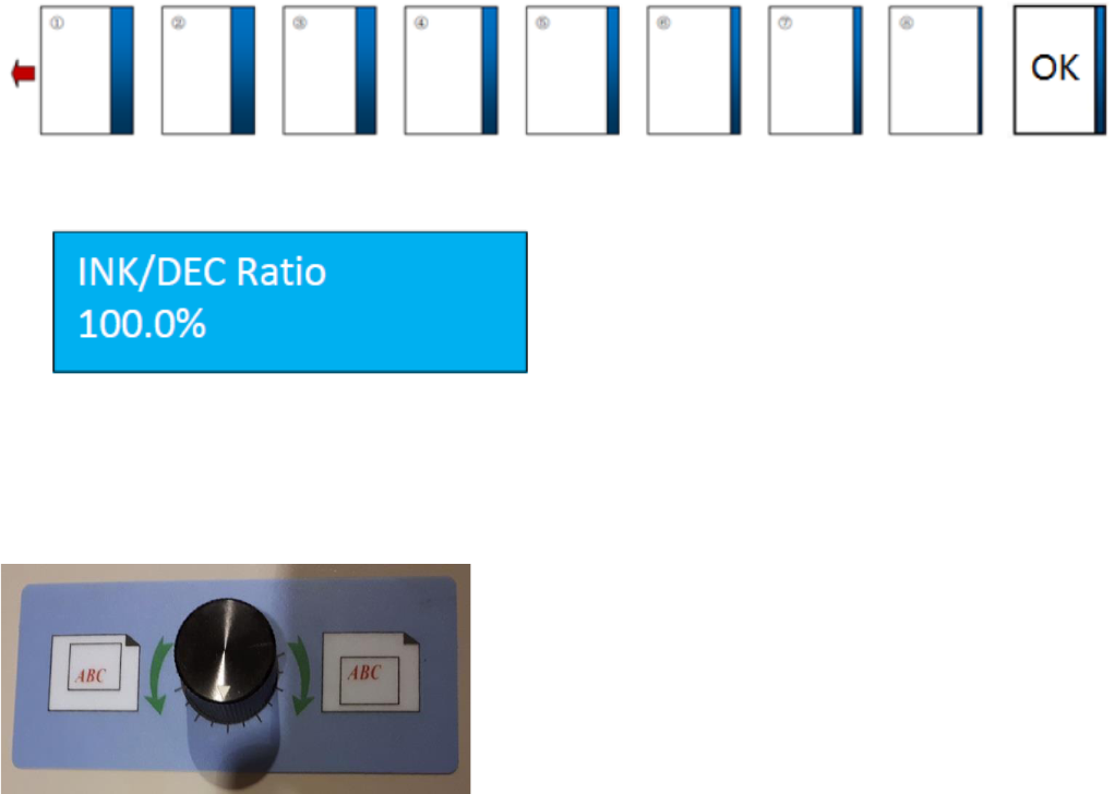
Set Shrink/Stretch Ratio
To compensate for printer image shift, the PT 331SCC is equipped with a
shrink/stretch feature. This function is designed to balance any image shrink
or stretch that may have happened while printing. This will shift cuts up or
down by a percentage without changing the card size.
Press Increase Key to increase the ratio by 0.1% or press Decrease Key to decrease the ratio by 0.1%. Press Enter
to save changes.
Horizontal Shift Screen
This function is designed to balance any image shift that may have occurred
while printing. This will move all cuts up or down by an equal amount without
changing the card size. Press the increase Key to increase the value by 0.1mm
(0.0039”) or press the decrease Key to decrease the value by 0.1mm. Press
Enter to save the changes.
Card Length Offset Screen
This function is designed to compensate for card length changes due to image
shift or print placement. It will increase or decrease the card size. Press the
Decrease Key to decrease the value by 0.1mm (0.0039”) or press the Increase
Key to increase the value by 0.1mm. Press Enter to save changes.
Gutter Offset Screen
To increase or decrease the cut gutter size for print offset, press the Decrease
Key to decrease the value by 0.1mm (0.0039”) or press the Increase Key to
increase the value by 0.1mm. Press Enter to save changes.
Note: To avoid a tail trim error, the last cut on the sheet must be smaller than 0.59” and larger than 0.197”.
All image compensations functions are limited by the PT 331SCC parameters, as follows:
• First Cut: 0.12” - 0.59” (3.2mm - 15mm)
• Gutter Cut: 0.12” - 0.59” (3.2mm - 15mm)
• Last Cut: 0.197” - 0.59” (5mm - 15mm)
Save Job Screen
Use this function to save a user specific template. The max storage is 30
templates. If a job has already been saved under the specified number, the PT
331SCC will request confirmation to override. Press enter to override. The
new job will be saved in that spot.
INK/DEC Ratio
100.0
%
Horizontal Shift
0
inch
Card L Offset
0
inch
Gutter Offset
0
inch
Save Job
Job No.
1

15
Speed Screen
The speed feature sets the speed mode of machine. 1 is low speed; 2 is high
speed. Press Enter to save selection for the current run. Note: The default
state is low. When the machine is restarted, the PT 331SCC will default to the
slow speed.
Crease + Slit Screen
The normal function of the PT 331SCC is to leave the slit motor off when
performing crease only jobs or jobs that do not require the function of the
slitters.
If the required job is jamming at the slitters, turning on this function will allow the slitters to rotate and feed the
paper through. To turn on the slit motor, select 1, turn off the slit motor, select 2. Press Enter to save changes.
Note: The default state is off. When the machine is restarted, the PT 331SCC will default to slit motor off.
Speed
1=
Low*
2=
High

16
5.3.4 Smart Input Mode
Smart Input Mode functions in the same manner as the Job Creator on the PT 335SCC units. A set of parameters is
required and from this set, the SCC will calculate the required cuts for the finished job.
The image below shows a sample layout, 3.5” x 2”. The parameters of the job are as follows:
Lead Trim: 0.3”
Card Length: 2.0”
Gutter Cut: 0.2”
When printing jobs for the PT 331SCC, the image should be centered on the sheet. The PT 331SCC feeder is
center registered. The slit gutters are fixed. The lead edge and the gutter cut indicate the distance of the first card
from the lead edge and the space between the cards. For the GW business card layout, the gutter is 0.2” and the
lead edge is 0.3”.

17
Create a Job with Smart Input:
As mentioned, there are several parameters that are required when using the Smart Input to set up a job:
Lead Trim – distance from lead edge to first cut
Card Length – length of the finished card (2” if creating a business card job)
Gutter length – distance between two images
To access the Smart Trim feature, Press the Mode Key 4. When Smart Input is
displayed, enter the value for the distance between the lead edge and the first
cut. For the Graphic Whizard business cards, this value is 0.3. Press enter to
advance to the next screen.
Next, enter the length of the finished job. For the standard North American
business card, the length is 2”. Press Enter. Key in the gutter length, the
distance between two images. For the GW business card template, this
distance is 0.2”.
If the job has creases, enter the position of the crease on the finished job. For
example, the GW 6 ticket job has the following PT 331SCC parameters:
Lead Trim: 1.5”
Card Length: 8”
Cut Gutter: 2.5”
Cross Perf (Crease): 2”
At the crease 1 prompt, 2.00 would be entered. It is not necessary to enter the next cross perf as the SCC will auto
program the crease based on the job parameters. If no creases are required, press enter to advance to the next
screen.
Note: A maximum of four creases can be programmed using Smart Input. If required, more creases can be
programmed after completing Smart Input.
When all the information has been entered, the display will return to the Ready screen.
Smart Input
Trim:
0.300
Length
2.000
Gutter
0.2
Crease1:
0
Crease2:
0

18
Tail Trim Error
A tail trim error occurs when the values entered do not fit the sheet length
and the tail trim is out of machine spec. The last cut range is 0.197” ~
0.591”. If the last cut is out of range, the SCC will display the tail trim error.
Ensure the sheet length, card length, and trim lengths are correct and try
programming the job again.
5.3.5 Job Layout Creation
Registration mark
The 331 SCC is designed to center register.
• When creating a print layout with a registration mark, ensure the mark is 5.484” from the center
of the sheet.
• The registration mark should be larger than 0.118” x 0.472” (3x12mm).
• Set the registration mark between 0.118” - 0.59” (3-15mm) from the leading edge.
• Do not have any colors above this mark or the reader may fail to correctly read the registration
mark.
5.3.6 Parameters
Minimum Cut from Lead Edge
0.125”
Maximum Cut from Lead Edge
0.59”
Minimum Cut from Tail Edge
0.19”
Maximum Cut from Tail Edge
0.59”
Minimum Slit from Side Edge
0.125”
Maximum Slit from Side Edge
0.59”
Minimum Gutter Cut
0.118”
Maximum Gutter Cut
0.59”
Fixed Gutter Slit Width
0.375”
Registration Mark
Specifications
0.118” x 0.472”
Registration Cut Mark Location
5.484” from the center of the sheet, 0.118”-0.59” from leading edge (Y direction
only)
Minimum Card Size
2” wide x 1.2” long
Note: The sample jobs to follow are based on 12” x 18” sheet size. For 13” x 19” sheets, adjust the lead cut and side
slit accordingly to keep the same layout, keeping within the parameters defined above.

19
5.3.7 Job Layout Parameters
12”x18” sheet

20
12”x18” sheet

21
12”x18” sheet

22
12”x18” sheet

23
5.3.8 How to Create a Register Mark
The PT 331SCC is designed to center register, however the registration mark reader is located on the non-operator
side of the PT 331SCC. When creating a print layout with a registration mark, ensure the mark is placed within the
following parameters.
The following diagram is for a 13” sheet:
• For a 12” wide sheet, the mark should be 5.484” from center.
• For a 13” wide sheet, the mark should be 5.984” from center. The sensor must be moved manually for
this setup.
• Register cut mark distance should be between 0.118” - 0.591” (3-15mm) from leading edge.
• The black mark should be more than 3x12mm (W>=0.472”, L>=0.118”) (W>=12mm, L>=3mm)
• The area above the mark should be blank. Any color could potentially interfere with the registration
mark reader.
• The register mark reference point is the top edge of the mark.

24
5.3.9 How to use a Register Mark
Press the Mode Key 3 times to enter the Register Mark Screen. Press the
number 1 on the keypad and press enter. This will activate the registration
mark feature. Pressing enter will also advance to the next screen.
Input the distance of the register mark from the lead edge of the sheet 0.2
to the top of the register mark. If needed measure the distance using
calipers. Pressing enter will advance to the next screen, Smart Input. If using
Smart Input, enter the job values when prompted. If not, press enter to
advance through the smart trim feature.
The square on the ready screen indicates the register mark feature has been
activated. To turn off the feature, press M until REG. Mark is displayed. Key
in 2 on the keypad and press Enter to save. Note: The Register Mark can only
be used with user defined templates. It will not work with the factory
templates.
5.3.10 Using the Cut Mark Registration
The PT 331SCC is equipped with a Cut Mark Reader. A cut mark is a solid black bar that is printed at the top of the
sheet, usually to the left-hand side. When the cut mark registration is used, the PT 331SCC will read the placement
of the cut mark and adjust the slitter and knife location to compensate for image shifting on the sheets. This helps
to ensure that each job is uniformly cut.
First, manually adjust the Cut Mark Reader (located internally before the
slitters) sliding the positioning knob to the proper sheet size (12” or 13”).

25
5.4 Hardware Setting
5.4.1 Side Guide Setting
Infeed Table
The minimum infeed paper width is limited to 6.5” (165mm). The maximum width is 13” (330mm).
Insert the paper by loosening the thumb screws
(shown in the above image) on the side guides
and slide the rails out.
Place 3-5 sheets on the table and snug the rails
tight against the paper. The guides should be
tight enough to prevent side shift but not so
tight the paper will not feed.
5.4.2 Positioning Slitters
The positioning of the slitters is shown in the following picture. The shaft on which the slitters are mounted have
lock positions. These lock positions have markings on the positioning shaft. Slide the slitter assemblies until they
‘click’ into the required lock position (3.5” or 5.5”). Position the collars against the slitters and tighten the set screws
to lock the slitters in place.

26
To custom set the slitter position, install the paper, and press the Test button. This will feed the paper in, stopping
just before the slitters. Set the slitter position according the job. Position the collars against the slitters and tighten
the set screws to lock the slitters in place.
5.4.3 Skew Adjustment
To adjust paper skew, loosen the two screws on the outside edges of the feed table (shown in the image above),
making sure the screws can move freely in the hole.

27
Using the gauge as a reference, adjust the screw
positions in the direction of the arrow to correct
skew.
Only micro movements are required. Test between
each adjustment until the skew is corrected.
5.4.4 Outfeed Tray Setting
The PT 331SCC ships with two long paper guide stops and one
smaller back stop. For straight crease jobs or larger finished output,
place the guides slightly wider than the finish product and line up
the back stop with the ends of the paper guide stops.
For business card jobs, place the business card
catchers against the exit of the PT 331SCC, in line
with the output.

28
5.5 Slitters Setting
While the slit gutters are fixed, the PT 331SCC slit positions can be customized to fit almost any job.
To make switching
between standard sized
jobs easier, the PT
331SCC is equipped with a
slitter placement gauge.
As a starting reference
the gauge is marked with
two standard widths: 3.5
(business cards, etc.) and
5.5 (greeting cards).
However, the arrow will
move if the side-shift
knob is used.
Set the slitters in the positions marked on
the gauge that match the desired job. Line
up the slitters with the notched positions
on the slitter shaft.
Slitters set to the red line will produce 3.5”
wide cards.
Slitters set to the green line will produce
5.5” wide cards.
Using the provided hex tool, secure the
position by moving the collars against the
slitters and tighten the set screws to lock
the slitters in place.

29
Use this quick set-up guide, located on the feed tray,
to assist in setting up the slitters.
5.5.1 Compensation for Image Shift Left/Right
The PT 331SCC is equipped with a manual side to side (left/right)
image shift adjustment. If the finished job is shifted left or right,
turn the knob in the correct direction to resolve the issue. Run a
test sheet to ensure the image is properly centered on the
finished job.

30
5.5.2 Side Trimming
Move the Slitters #1 and #4 all the way to the side. Slitter #2 and Slitter #3 will be used to trim the sides. Since they
are a fixed gutter slitter, the amount of trim that can be done has the same limitations. Trying to trim less than
3.2mm (0.126”) will be too thin and the waste will not go into the bin and can get stuck in the slitter head.
Trimming 3.2mm (0.126”)-10mm (0.375”) is OK as the waste is thick enough and will go into the waste bin.
Trimming from 10mm-15mm will cause a similar issue. The paper under the 10mm position will go into the waste
bin but the paper outside the second slit (10mm-15mm position) can get stuck in the slitter head but everything
past the 10mm position will come out the exit rather than going to the waste bin.

31
5.5.3 Paper Deflectors
The PT 331SCC is equipped with deflector rollers. These rollers help compensate for paper drop as the sheets pass
through the slitter section. The deflectors should be centered in the machine.
5.5.4 Set Crease Data
• To set the crease parameters, press the Mode Key 6 times, or until Input CR Data is displayed on the screen.
A total of 32 creases can be programmed.
• Input the crease values, pressing Enter between each value to advance to the next line.
• When all values have been programmed, press the Enter button a second time. This will return the 331SCC
to the ready screen.
5.6 Side-Sheet Trimming
5.6.1 Slitter Placement
Set the slitter positions either through the gauge template or manually. When running trim only or trim with crease
jobs, use Slitters 2 and 3 for the trim.
For side trims, the waste trim should be either 0.118”-0.236” (3-6mm) or larger than 0.59” (15mm) to compensate
for the fixed slit gutter. If the side trim is between 0.236” and 0.551”, or less than 0.118”, there is a risk of the paper
pieces getting caught in the slitter blade assembly, potentially causing a jam. Trim larger than 0.59” will not be
diverted to the waste bin and will feed out the exit with the finished job.

32
5.6.2 Set Cut Data
With the slitters in the correct position for the trim job and the register mark function set to off, use the PT 331SCC
programming to set the cut positions.
• Press the M button until Set Cut Data is displayed on the screen. A total of 32 cuts can be programmed for
a single job.
• Set the cut positions according to the job parameters, pressing enter between each value.
• Press Enter twice when all cuts are programmed to return to the Ready screen.
• Place the exit tray and paper guides in place to catch the finished job as it exits the PT 331SCC.
5.7 Slide-in Tools
The PT SCC is equipped with a cross crease and/or cross perf function. The tools are comprised of two pieces. For
the crease tools, orientation is not an issue. The crease can be set to crease up or crease down, depending on the
job requirements. The cross perf tool must always be placed with the rubber crash pad in the bottom slot and the
perf blade tool in the top slot.
To remove the tools:
1. Open the side access cover by loosening the top and bottom screws enough to let the cover swing
down.
2. Pull the tools out by gripping the black tool knob. There is no release latch for the crease tools. The
tools should slide in and out, clicking into place when fully inserted.
3. Store the tools in the tool holder located just under the power plug of the PT 331SCC.
Note: the tools do not have to be in place for the PT 331SCC to function.

33
5.7.1 Change Perforate Crash Pad
The cross perf crash pad is a consumable item and will require replacement. To maintain the life of your perf blade,
please check the perf anvil regularly and replace the crash pad if worn.
To replace the crash pad:
1. Remove the crash pad anvil tool
from the PT 331SCC (installed)
2. Peel up one edge of the crash
pad and pull along the length of the tool.
3. Clean any glue residue from the
anvil tool.
4. Peel the protective backing from
the replacement crash pad.
5. With the anvil clean, carefully
adhere the replacement crash pad to the
anvil.
Note: The anvil will need to be exercised to
achieve a clean perforation. Run a 12”x18” job
with at least 10 cross perfs programmed. Run this
job 20 times.

34
5.7.2 Crease Depth Adjustment
Crease depth is important for crease quality and should be adjusted according to the paper thickness. It may also
be necessary to adjust the crease depth when switching between the cross-crease tool and the cross-perf tool.
Low crease depth will create a light crease and too much crease depth may cause cracking. The depth should be
balanced across the crease tool.
To adjust the crease depth:
1.
Open the top
cover
2.
Using a 5mm hex tool, turn the crease
depth screws in the direction of the
desired depth. If the crease is too light,
turn the screws toward t
he deeper
impression. If the crease is too deep, turn
the screws
toward the lighter impression.
3.
Work in quar
ter turns for both sides. Test
between each adjustment until the desired
crease is attained.
Too heavy
Not balanced
Cracked edge
Too
light
Normal

35
5.8 Slitter Removal and Replacement
Complete the following steps to remove the slitters.
Note: this procedure is applicable for both the 331SCC manual and 331SCC Air
1. Power down the 331SCC. This is for safety.
2. Locate the slitter removal tools that were shipped with the 331SCC. There should be two thumb screws
and two notched plates.
3. If installed, remove the template. You now have access to the slitter assemblies.
4. Loosen the two countersunk screws, if removing slitter assembly 1 or 4, or four screws if removing sitter 2
or 3, that secure the upper slitter assemblies to the lower assembly.
5. Carefully lift the slitter assembly.
6. Clean out the upper and lower assemblies.
7. Skip to Slitter blade removal if removing blades. This covers the lower slitter assembly removal procedure.
8. When all dust and debris has been removed from the upper and lower assemblies, install the thumb screws
in the center of the upper slitter assembly.

36
9. Insert the notched plates between the slitter removal shaft and bearings by pulling on the thumb screws.
The slitter blades are spring loaded.
10. The upper slitter blades rest outside of the lower blades. When installing, ensure the blades remain to
the outside by pinching the notched plates in or pulling on the thumb screws. Note: you may need to
move the other slitter assemblies to create room for the thumb screws.
11. Tighten the screws, keeping the tools in place to ensure the blades don’t shift out of position.
12. Run a test sheet. If the slit is jagged, loosen the screws and adjust the slitter blades by pulling on the thumb
screws.
13. Continue testing until the slitters produce a clean slit.
14. Remove the notched plates. Remove the thumb screws.
15. Test the 331SCC for clean slits.

37
5.9 Slitter Blade Removal Procedure
1. Complete the steps listed above, stopping at step 6.
2. Remove the op and non-op side covers.
3. Locate and remove the slitter side cover from the op and non-op side.
4. Remove the slitter drive belt. You can remove the gear as well, but it’s not necessary.
5. Remove the brackets securing the slitter drive assembly to the chassis.

38
6. Carefully remove the entire assembly from the machine. You now have access to all four slitter assemblies.
7. Remove the 2 screws securing the deflector plate.
8. The slitter blade hub can be removed by sliding the slitter drive rod through the hub. Note: there is a T-pin
that fits into the groove in the slitter drive shaft.
9. Replace the blades on the hub. When reinstalling the hub, ensure the pin is present and slotted into the
groove. This is required for all hubs.
10. Reinstall the deflector plate.
11. Install the upper slitter assembly as per the instructions above.
12. Install the slitter drive assembly into the chassis and secure with the brackets.
13. Attach the drive belt and gear.
14. When everything is secure, run a test page. If the slit is jagged, follow the instructions above, testing
between each step.
15. When the slits are clean, your work is done.

39
Chapter 6 Trouble Shooting
6.1 Error and Warning Codes
The PT 331SCC has built-in error and warning indicators. When an error or warning is encountered, the coinciding
LED will flash. The PT 331SCC has the following indicators:
C Errors are checks and E Errors are faults
6.1.1 Warning
C – 1 Top Cover Open
The top cover warning is accompanied with a flashing red light below the cover
open icon on the keypad.
If the cover is closed, open the cover, and check the position of the cover
switch. The tab on the cover should activate the switch when closed. The cover switch is located on the operator
side of the PT 331SCC, opposite the keypad.
Test the function of the switch by pressing on the
tab with the cover open. If the error clears, try
closing the cover again. If the error remains with
the cover closed, loosen the two screws that secure
the switch to the chassis of the PT 331SCC and
adjust the position of the switch. When the correct
height is attained, tighten the screws.
If the cover open indicator remains on with the
switch activated, contact your local GW service
dealer for technical support.
C
–
1
Top Cover Open.

40
C – 2 Paper Jam at Infeed Roller
The infeed sensor is located inside the top cover, just after the infeed roller
belt assembly.
The infeed sensor is looking for the paper sheet to pass through and clear the sensor in a certain length of time. If
the sensor is not cleared within the allocated time, the paper jam at infeed error will display and the paper jam
indicator will come on. The SCC will stop. Check for paper jammed in the slitters. Clear any jammed paper from the
slitters by carefully pulling out the paper. Use the forward and reverse buttons to move the paper through the SCC.
The cover should be closed when using the paper advance buttons.
• Check for scrap paper under the sensor. Clear out any loose paper. Empty the waste bin.
• If the paper is stopping at the slitters, make sure slitter motor is turned on. See page 14 section “Crease &
Slit Screen”
• Clean out the sensor with compressed air or with a soft, dry, lint-free cloth.
• Check the quality of the paper before running the job again.
C – 3 Paper Jam at Outfeed Roller
The outfeed sensors are located at the exit of the PT 331SCC.
Ensure the finished paper is clearing the exit sensors. If running a business
card job, watch the cards as they exit the machine. If they are getting stuck
on the deflectors, reform the deflectors by pressing down with your thumbs to create a sharper angle. Empty the
card catchers if full.
For non-business card jobs, ensure the cards have
enough room to clear the exit and drop cleanly to
the exit tray. The sensors are located at the very
edge of the exit. It does not take much for the
sensors to be tripped by finished stock.
• Clean the sensors with compressed air.
• Remove any paper jams using the same procedure as defined under the infeed jam error.
• Ensure the actual paper length matches the length of the sheet as defined in the job parameters.
C
–
2
Jam at Infeed.
C
–
3
Jam at Outfeed.

41
6.1.2 Error
E-1 Crease Motor Error
A Crease Motor Error indicates the PT 331SCC has encountered an error with
the crease motor. The crease motor error is a hard fault. The machine will not
run until this error has been resolved.
• Power off and on the SCC to reset the machine. Any paper caught in the SCC will be cut when the cut motor
test runs on power up.
• Press the paper advance button to move the paper though the crease section. If the paper is sticking out
of the machine exit, try pulling the paper while pressing the paper advance button to assist in paper
extraction.
• Press the advance button until all paper has been cleared.
• Check the crease job depth. If too heavy, adjust the crease depth. Ensure the paper is within machine specs.
• Remove the crease tools and check for paper that may be caught in the crease section. Clear any scraps.
• If the error appeared on power on, try powering on the unit again.
• If the error persists and no paper is found in and around the crease section, contact your local GW dealer
for service.
• Run several crease tests to ensure the unit is functioning.
E-2 Cut Motor Error
A Cut Motor Error indicates the PT 331SCC has encountered an error with the
cut motor and is a hard fault.
• Power on and off the SCC to reset the machine. Any paper caught in the SCC will be cut if the restart
successfully cleared the fault. Press the advance button to clear any remaining paper.
• Check for paper scraps around the knife assembly. Clear any scraps. Empty the waste bin.
• If the SCC continues to present the error after a restart, contact your local GW dealer for service.
E
–
1
Crease Motor Error.
E
–
2
Cut Motor Error.
42
6.2 Image Compensation
Image compensation helps correct image shift that might have occurred during printing.
Cut Shift Correction
If the job has a registration mark, ensure the mark reader is set to On and the position of the registration mark has
been programmed into the job. Run a test using the register mark and check the image on the cards. The image
below shows an example of image shift.
Press the Mode button until INK/DEC Ratio is displayed. If
no adjustment has been made, the value will be 100%.
Increase or decrease the value by pressing the forward
and backward buttons. The value will change by 0.1% with
each button press. Run a test with each adjustment. All
changes will be saved with a power reset.
Manual Side to Side Adjustment
If the image of the finished job is not centered or requires left
to right adjustment, the PT 331SCC has a manual side to side
adjustment feature.
Before adjusting, ensure locking collars are secured on either
side of the slitter by tightening the set screws. Run a test sheet.
Adjust the slitter position by turning the adjustment knob left or
right, in the direction of the required adjustment. Run test
sheets until the image is centered.

43
Chapter 7 Maintenance
To extend the life of the PT 331SCC, regular maintenance should be performed.
User Maintenance
• For a deep clean, use the GW roller cleaner. Wash rollers with water after the roller cleaner.
• Clean Sensors with compressed air or a soft cloth.
• Check the PT 331SCC regularly for paper scraps and debris.
• Lubricate the roller bushings with a 3-in-1 oil.
• Add a touch of grease on the knife guide.
• Lubricate the knife pivot points and springs with a 3-in-1 oil after every 200,000 cuts.
• Empty the waste bin after every job or if the PT 331SCC starts jamming.
• Contact your local GW dealer for preventative maintenance and service.
